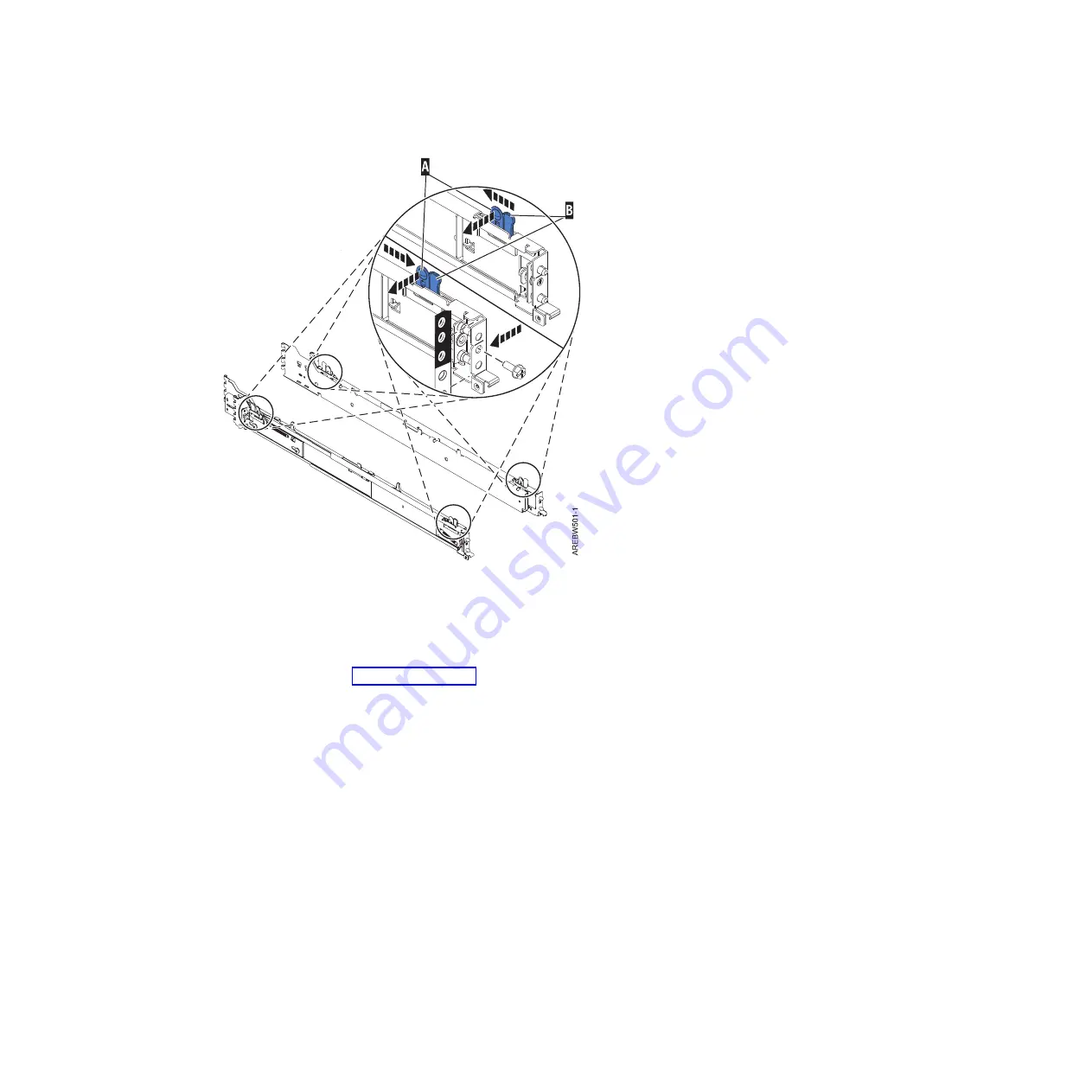
3.
Align the back-alignment pins of the rail with the holes at the back of the rack identified by the
self-adhesive placement dots on the back of the rack. Ensure that the rails are level.
4.
Slide the release tab
(B)
to extend the two back-alignment pins into the back of the rack. Ensure that
the pins have passed through the correct holes in the rack frame.
5.
From the back of the rack, as shown in Figure 37 on page 44, install the rail support bracket on the
alignment pins. Then insert a large rail-retaining screw into the hole that is located between the two
back alignment pins. Partially tighten the screw. Do not tighten completely at this time.
Note:
The brackets are labeled left and right. In this illustration, these brackets are shown in blue for
emphasis.
Figure 36. Front slide rail alignment pin
Chapter 3. Installing a system or expansion unit into a rack
43
Summary of Contents for 0551
Page 1: ...Power Systems Rack rack features and installing systems or expansion units into a rack ...
Page 2: ......
Page 3: ...Power Systems Rack rack features and installing systems or expansion units into a rack ...
Page 8: ...vi Installing into a rack ...
Page 12: ...2 Installing into a rack ...
Page 34: ...24 Installing into a rack ...
Page 118: ...108 Installing into a rack ...
Page 126: ...116 Installing into a rack ...
Page 130: ...120 Installing into a rack ...
Page 148: ...138 Installing into a rack ...
Page 164: ...154 Installing into a rack ...
Page 174: ...3 Close the front rack door 164 Installing into a rack ...
Page 181: ......
Page 182: ... Printed in USA ...


