background image

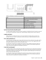
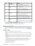
LED

Description

Definition

1

Identify

Blue— Disk drive module is being identified.

2

Fault

Off— The disk drive module is operating normally.
Amber— A fault has been detected or a service action is

required.

The replacement procedure should be completed within an absolute maximum of 3 minutes. For

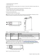
additional information about SFF disk LED behavior, see “Disk drive carrier module LEDs” on page 57.

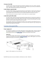
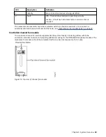
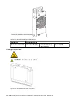
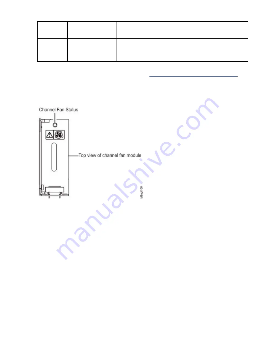
Controller channel fan module

The controller channel fan module supplements the system fans by circulating airflow within the

enclosure controller channel, and providing additional cooling for the IOMs/EBOD expander modules. The

replacement procedure should be completed within an absolute maximum of 3 minutes.

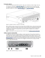
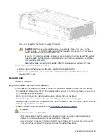
Figure 20. Top view of channel fan module

Chapter 3. System Overview  23

Summary of Contents for 106

Page 1: ...IBM ESS expansion Version 5 3 5 Hardware Installation and Maintenance Guide Model 106 IBM SC27921101...

Page 2: ...l notices on page xiii The information in the IBM Environmental Notices and User Guide provided on a DVD This edition applies to IBM ESS expansion Model 106 and is valid until replaced by new editions...

Page 3: ...nclosure front panel 9 Enclosure rear panel 10 Rear panel components 10 Enclosure top panel 12 Enclosure chassis 14 Overview of front panel LEDs 14 System Power On Standby LED green 15 Identify LED bl...

Page 4: ...olving 55 Overview 55 Initial start up problems 55 Faulty power cords 55 Computer does not recognize the enclosure system 55 LEDs 56 PSU LEDs 56 Front panel LEDs 56 Disk drive carrier module LEDs 57 E...

Page 5: ...lared Noise Emissions in Accordance with ISO 9296 1 2 3 84 Environmental requirements 84 Power supply unit PSU module 85 Appendix B Standards and regulations 87 International standards 87 Potential fo...

Page 6: ...Russia Electromagnetic Interference Class A Statement 100 Homologation statement 100 vi...

Page 7: ...odel 106 expansion enclosure top panel with covers not shown 13 11 Model 106 enclosure top panel module slot index diagram 13 12 Front panel lower left corner partial view 15 13 PSU oriented for use i...

Page 8: ...32 Fastener detail 37 33 Attachment spring detail 37 34 Front rack post attachment details 38 35 Attachment spring 38 36 Rack post square hole location detail 39 37 Not good example 40 38 Good example...

Page 9: ...abling method 51 59 Typical AC power cord connection from PDU to PSU 52 60 Top view of LFF disk drive module 57 61 Removing a PSU 1 of 2 69 62 Removing a PSU 2 of 2 70 63 Removing a system fan 1 of 2...

Page 10: ...ving an IOM EBOD expander module 2 of 2 80 76 Unpacking the enclosure 3 piece box with packing 91 77 Unpacking the enclosure RSC box with packing 92 78 Unpacking the enclosure 3 piece box with packing...

Page 11: ...06 product components for Model 106 drive chassis 63 10 Part numbers of Customer replaceable units 63 11 Model 106 product FRU components for Model 106 drive chassis 65 12 Part numbers of Field replac...

Page 12: ...xii...

Page 13: ...ed the power cord s connect power to this unit only with the IBM provided power cord Do not use the IBM provided power cord for any other product Do not open or service any power supply assembly Do no...

Page 14: ...epair or disassemble C003 Use the following general safety information for all rack mounted devices DANGER Observe the following precautions when working on or around your IT rack system Heavy equipme...

Page 15: ...nt of the supply circuit For sliding drawers Do not pull out or install any drawer or feature if the rack stabilizer brackets are not attached to the rack Do not pull out more than one drawer at a tim...

Page 16: ...equired environmental notices for IBM Systems products in English and other languages The IBM Systems Environmental Notices information includes statements on limitations product information product r...

Page 17: ...thod of contacting the IBM Support Center In the United States Call 1 800 IBM SERV for support Outside the United States Contact your local IBM Support Center or see the Directory of worldwide contact...

Page 18: ...xviii IBM ESS expansion Hardware Installation and Maintenance Guide Model 106...

Page 19: ...7 and fits a 1 2 m rack It conforms to CFF Common Form Factor for canister bay support and it integrates with IBM ESS Data Server 5104 22C The integral Cable Management Arm CMA allows the enclosure t...

Page 20: ...2 IBM ESS expansion Hardware Installation and Maintenance Guide Model 106...

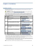
Page 21: ...the site for installation per Installation checklist and follow safe handling instructions provided in Unpacking the enclosure on page 29 Permanently unplug the enclosure before you move it or if you...

Page 22: ...of data or system damage may result if IBM service does not perform the relocation action Shipment or storage conditions that exceed the specified limits can cause permanent damage to your server Thes...

Page 23: ...uation The customer supplied facilities voltage must maintain a voltage with not more than 5 percent fluctuation The customer facilities must also provide suitable surge protection Important The enclo...

Page 24: ...nt temperature for the enclosure which is 35 C 95 F for JBODS EBODs Above an altitude of 900 meters derating applies as per ASHRAE Class A2 The rack should have a safe electrical distribution system I...

Page 25: ...r Each individual disk drive is hot pluggable and replaceable on site Drive modules must be installed during system setup Note Throughout this guide and the management interface documents used with th...

Page 26: ...ure variants Product Description of configuratio n PSUs1 Systemfans2 IOMs EBOD expander modules3 IOMfans EBOD expander module fans2 Disks4 HSExpanders 5 Model 106 12Gb s direct dock LFF 2 4 2 2 106 8...

Page 27: ...CMA for managing cables and enabling in rack servicing of the enclosure Note About enclosure modules The disk modules are not installed when the enclosure ships Do not insert disks into the enclosure...

Page 28: ...1 Right ear assembly as viewed from back 2 System fan module quantity 4 3 Power supply unit quantity 2 4 Cable shelf and CMA bracket for coiled cables 5 IOM EBOD expander module quantity 2 6 Left ear...

Page 29: ...ore inserting it into the slot as shown in Figure 4 on page 10 Figure 6 IOM EBOD expander module detail Power supply unit Figure 7 on page 11 shows the power supply unit used in a Model 106 enclosure...

Page 30: ...access to IOMs EBOD expander modules C fixed cover does not remove It provides protection for the IOMs EBOD expander modules Figure 9 Model 106 expansion enclosure top panel with covers installed Fig...

Page 31: ...ulated in all cases The acronym DDIC Disk Drive In Carrier is used as a synonym for disk drive module Populating disk drive slots The Model 106 does not ship with pre installed disk drive modules When...

Page 32: ...dplane to 24HDD baseplanes Four 24 HDD baseplane PCBs support 96 disk drive connections in the drive channel 10 HDD baseplane PCB supports 10 disk drive connections in the controller channel The enclo...

Page 33: ...nd the LED is not blinking there is a possibility of a disk drive fault This LED can be used together with other Fault LEDs to determine whether a drive fault condition exists Pull the chassis forward...

Page 34: ...faulty component within the controller channel This LED is normally off and illuminates only when a fault occurs with a component beneath the top lid on the left Pull the chassis forward from its inst...

Page 35: ...y modules missing will disrupt the airflow and the disks will not receive sufficient cooling It is essential that all slots are fitted with PSUs prior to powering on the enclosure Important To avoid p...

Page 36: ...ure is reported as a dual fault System fans are hot pluggable and replacement should only take a few seconds Replacement must be completed as soon as possible after the removal of the defective system...

Page 37: ...gurations are detected The replacement procedure should be completed within an absolute maximum of 3 minutes Note For a description of the expansion enclosure canister LEDs see 12Gb s expansionmodule...

Page 38: ...o view LEDs of components that are accessible from the top panel you must first remove the lid for the compartment in which the component is installed The enclosure top panel is shown in Figure 9 on p...

Page 39: ...disk drive slots located on the enclosure top panel Figure 17 LEDs Dual path LFF 3 5 disk drive carrier modules top panel LED Description Definition 1 Identify Blue Disk drive module is being identifi...

Page 40: ...Figure 19 DDIC aligned to module slot 22 IBM ESS expansion Hardware Installation and Maintenance Guide Model 106...

Page 41: ...tes For additional information about SFF disk LED behavior see Disk drive carrier module LEDs on page 57 Controller channel fan module The controller channel fan module supplements the system fans by...

Page 42: ...or states Channel Fan Status LED Channel Fan OK Off Fan fault ID Amber blinking amber Power off Off HS Expander module CAUTION A hot surface nearby L007 Figure 22 HS Expander module top panel 24 IBM E...

Page 43: ...r SEP that provides a SES target for a host to interface through the ANSI SES Standard If one of these modules fails the other module will continue to operate Refer to a module s specification or the...

Page 44: ...26 IBM ESS expansion Hardware Installation and Maintenance Guide Model 106...

Page 45: ...precautions on page 67 4 Install the Model 106 into the rack space See Installing the 4U enclosure 5 Cable the Model 106 to the compatible server HBA or RBOD See unique_58 unique_58_Connect_42_fig_kjs...

Page 46: ...0 and an IOM blank must be installed in IOM slot No 1 Disk drive module Top panel See Populating disk drive slots on page 13 Channel fan Top panel Up to two channel fan modules of the same model type...

Page 47: ...iarize yourself with the exploded view of packaging components that pertain to your enclosure product See also Appendix C Enclosure packaging on page 91 1 Examine the packaging for crushes cuts water...

Page 48: ...tic bag are shown They are isolated from the remainder of the packaging As a visual aid for this unpacking task see Appendix C Enclosure packaging on page 91 for more information about the packaging m...

Page 49: ...rements for rackmount installation You can install the enclosure in an industry standard 1 2m cabinet capable of holding 4U form factors Minimum depth 1 206 5 mm 47 5 from rack posts to maximum extrem...

Page 50: ...del 106 enclosure rails and rack Warning Do not attempt to install the enclosure into the rack with disks preloaded into drive slots Unload disks if installed and CRU modules to a static protected are...

Page 51: ...ce Attachment holes for Step No 3 are identified in the above figure 4 Relocate the right rail mounting bracket to approximately match the rack post to post distance recorded in step 1 This bracket ha...

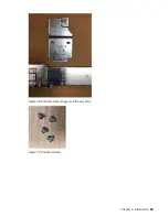
Page 52: ...identified above 7 Using the quantity 4 panhead screws provided with the CMA kit attach the CMA attachment bracket to the rear end of the outer slide on its outside surface The following images show t...

Page 53: ...Figure 28 CMA attachment aligned with outer slide Figure 29 Panhead screws Chapter 4 Installation 35...

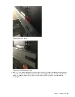
Page 54: ...t ensuring that the rail subassembly occupies the lower 2U portion of the allotted 4U space The rear mounting bracket spring will clip onto the rail Ensure that the quantity 2 all in one rail kit moun...

Page 55: ...o the rack post ensuring that the rail subassembly occupies the lower 2U portion of the alloted 4U space The front mounting bracket spring will clip onto the post Ensure that the quantity 2 all in one...

Page 56: ...Figure 34 Front rack post attachment details Figure 35 Attachment spring 38 IBM ESS expansion Hardware Installation and Maintenance Guide Model 106...

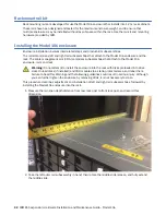
Page 57: ...into the rack in the second to top and third to top square holes in the 4U space mates to thumbscrew and panhead screw in step 21 Figure 36 Rack post square hole location detail 13 While heeding the f...

Page 58: ...ass Using the lift for this purpose could damage rails Do not bend the middle rail in order to force alignment with the inner rail Alignment should be adequately established with the lift If fine tuni...

Page 59: ...moothly onto inner rails Difficult middle slide movement during this step typically indicates misalignment 17 Middle rails will eventually click into place as the service position locks engage Ensure...

Page 60: ...side For shipping and transport secure the 10 32 panhead screws provided and torque to 3 96 N m 35 lbf in quantity 4 2 per side 22 Using the quantity 2 panhead screws provided attach the CMA chassis a...

Page 61: ...mbly CMA attachment bracket from step 7 Ensure that the blue spring clips onto the C shaped CMA attachment bracket securely and the arrow next to the B mark on the CMA arm is pointed upward The B brac...

Page 62: ...hat the blue spring clips onto the C shaped CMA attachment bracket securely The A bracket should reside inside the CMA ramp lip as shown above 25 Install the crossbar Figure 49 Crossbar with blue thum...

Page 63: ...and in rack servicing of the enclosure This section provides instructions for routing cables through the CMA to include using the CMA baskets and the CMA storage shelf located at the rear of the enclo...

Page 64: ...Figure 50 Rear view Figure 51 Top view 46 IBM ESS expansion Hardware Installation and Maintenance Guide Model 106...

Page 65: ...ecure the rest of the data cables The outer CMA cable capture arm may need to be pushed down in the C bracket to allow the inner cable capture arm to seat properly The CMA bracket may need to be shift...

Page 66: ...U cable clip assembly and set it aside for re installation b Install the right angle C19 connectors into the PSUs c Route the cables as shown ensuring they lay flat on the CMA shelf and through the PS...

Page 67: ...t two baskets ensuring minimal cable crossover to maximize space b Use all available space on the CMA shelf to make the first 180 bend into the first CMA basket c Keep pairs of dual SAS cables paralle...

Page 68: ...er additional or longer cables when cabling a fault tolerant configuration SAS topology The star configuration topology of SAS is supported with the Model 106 enclosure The star configuration has each...

Page 69: ...abling method An advantage of the star configuration is that each expansion enclosure is only one additional expander or hop away from the initiator This reduces delays in the SAS communication path T...

Page 70: ...e you remove the PSU from the enclosure Whether standard single lead or bifurcated Y lead power cords must only be connected to a supply range of 200 240V AC as indicated on each PSU s hazardous volta...

Page 71: ...ks in the drive enclosure have enough time to completely spin up before being scanned by the controller modules within the controller enclosure While enclosures power up their LEDs blink After the LED...

Page 72: ...sure Removing the drives prevents damage to the drives and makes the lighter enclosure easier to move Unit Identification Number Software SES The enclosure serial number can be displayed using the mml...

Page 73: ...and I O Note For further troubleshooting help after setup and when data is present contact technical support Overview ESS software interacts with the Storage Enclosure Processor SEP and performs monit...

Page 74: ...s Under normal conditions the bitonal PSU Status OK LED will be a constant green See also Figure 13 on page 16 When a fault occurs the color of the LEDs will display as shown in the following table Ta...

Page 75: ...sion module LEDs IOM EBOD expander module status is monitored by the LEDs located on the faceplate See also Figure 16 on page 19 LED behaviors for expansion enclosures are described in Table 7 on page...

Page 76: ...h of the storage system Exceeding the limits of critical values will cause a notification to occur Troubleshooting The following sections describe common problems that can occur with your enclosure sy...

Page 77: ...data content Alarm messages are signaled by the SES pages page 29 PSU and system fan faults Symptom Cause Recommended action Front panel Module Fault LED is amber1 Any power fault Verify AC mains conn...

Page 78: ...ive re circulation of heated air from rear to front Use of the enclosure in a fully enclosed rack is not recommended 4 Verify that all blank modules are in place 5 Reduce the ambient temperature Therm...

Page 79: ...orrective action more quickly Determine where the fault is occurring When a fault occurs the Module Fault LED located in the lower left corner of the enclosure front panel illuminates See also Overvie...

Page 80: ...dule is replaced Note Model 106 enclosures support hot plug replacement of redundant expansion enclosure canisters power supplies fan modules and HS expanders Hot add replacement of expansion enclosur...

Page 81: ...torage capacity SAS SATA SSD 2 DDIC 2 5 SFF with adapter disks of differing type speed and storage capacity SAS SATA SSD Top 2 Power supply unit PSU module available as AC unit chassis uses two PSUs o...

Page 82: ...r Cables 001LU172 1 The Access column lists the enclosure panel from which the CRU is observed and accessed It does not apply to other components 2 See Enclosure chassis on page 14 for a description o...

Page 83: ...W b Cable Management Arm CMA and brackets Table 12 Part numbers of Field replaceable units Part Part Desc Substitute Part 001LU187 Kit Slide Rails 001YK763 Kit Slide Rails 001LU187 001YK729 Kit Slide...

Page 84: ...66 IBM ESS expansion Hardware Installation and Maintenance Guide Model 106...

Page 85: ...of the removal of a defective module Do not remove a faulty module unless you have the replacement module available and ready for insertion into the slot ESD precautions DANGER Multiple power cords Th...

Page 86: ...xible straps with a minimum of 1megohm 10percent resistance in the ground cords To provide proper ground wear the strap snug against the skin If an ESD wrist strap is unavailable touch an unpainted su...

Page 87: ...PSUs at once 3 Disconnect the power cable from the PSU power connector to power off the faulty PSU it has no power switch Note Power cables are typically routed to the PSU from the cable management ar...

Page 88: ...s the PSU to its connector on the back of the power midplane 4 Connect the power cable to the power source and the PSU Power cables are typically routed to the PSU from the cable management arm CMA Ve...

Page 89: ...ic protection Tip The illustrations show system fan module replacement as you face the enclosure rear panel See also Figure 4 on page 10 and Figure 8 on page 12 Removing a system fan module CAUTION Re...

Page 90: ...thin an absolute maximum of 2 minutes for this CRU module Replacing a controller fan module This section provides procedures for replacing a failed controller fan module Illustrations in controller fa...

Page 91: ...f 2 2 With your other hand grasp the handle located on the top of the fan and pull upwards to remove the fan from its slot as shown in Figure 66 on page 73 Figure 66 Removing a controller fan 2 of 2 I...

Page 92: ...one HS Expander module See CAUTION bullets regarding electrostatic discharge and anti static protection Tip The illustrations show HS Expander module replacement as you face the enclosure front and vi...

Page 93: ...ing a drive carrier module A disk drive module consists of a disk in a carrier or sled Disk Drive in Carrier DDIC modules are hot swappable which means they can be replaced without halting I O to the...

Page 94: ...dle towards the handle hinge to release the carrier handle as shown below Figure 69 Removing a LFF disk drive module 1 of 2 2 Revolve the handle outward to cam the module out of its connector on the b...

Page 95: ...should be revolved such that its horizontal axis is parallel to the chassis longitudinal axis as shown Figure 72 Installing a LFF drive carrier module 1 of 2 3 Slide the drive carrier fully into the d...

Page 96: ...ring off the enclosure In this case the second module provides paths to the drives until you install the new module You may need to replace an expansion module when The Fault LED is illuminated Logs o...

Page 97: ...tions in the IOM EBOD expander module replacement procedures show rear panel views of the enclosure and IOMs EBOD expander modules are properly aligned for insertion into the rear panel of the enclosu...

Page 98: ...e the IOM EBOD expander module for damage and closely inspect the interface connector Do not install if the pins are bent 2 Grasp the IOM EBOD expander module using both hands and with the latch in th...

Page 99: ...expansion enclosures the replacement expansion module may take up to one minute to initialize after the cables are connected Verify that there are no illuminated Fault LEDs on the enclosure front pane...

Page 100: ...82 IBM ESS expansion Hardware Installation and Maintenance Guide Model 106...

Page 101: ...Up to 0 8 kg Up to 1 8 lb Power Supply Unit PSU 1 45 kg 3 2 lb System fan module 0 7 kg 1 5 lb IOM EBOD expander module 0 8 kg 1 8 lb IOM EBOD expander module fan module 0 345 kg 0 8 lb HS Expander mo...

Page 102: ...and your server installation This IBM system is available with an optional acoustical door feature that can help reduce the noise emitted from this system The actual sound pressure levels in your inst...

Page 103: ...n positive Z axis OR ISTA 3H mounted in a rack horizontal impact on all sides 4 in drop tests Vibration operating 0 18 Grms 5 Hz to 500 Hz 30 min per axis Vibration non operating 0 54 Grms 6Hz to 200...

Page 104: ...50 load Harmonics Meets EN61000 3 2 EU EN 31000 3 3 EU EN 55024 EU KN 24 KN 35 S Korea Output 12V 164A 12V Standby Voltage 3 5A Hot pluggable Yes Switches and LEDs AC power cable connect and one bi t...

Page 105: ...interference at his or her expense Properly shielded and grounded cables and connectors must be used in order to meet FCC emission limits The supplier is not responsible for any radio or television i...

Page 106: ...specifications 1 United States and Canada Must be NRTL Listed National Recognized Test Laboratory e g UL Cord type SVT or SJT 14 AMG 3 conductor 2 0M max length Plug NEMA 6 15P grounding type attachm...

Page 107: ...atteries energy efficiency environmental making for batteries WEEE China RoHS environmental notice user guides and chemical usage Recycling of Waste Electrical and Electronic Equipment WEEE At the end...

Page 108: ...90 IBM ESS expansion Hardware Installation and Maintenance Guide Model 106...

Page 109: ...ead the documentation provided in your ship kit before unpacking disposing of or storing packing materials See also Unpacking the enclosure on page 29 Figure 76 Unpacking the enclosure 3 piece box wit...

Page 110: ...e configuration it does not include the rail kit box CMA box or accessory box These items are provided separately for this configuration Important Disk drives in carriers DDICs are packaged separately...

Page 111: ...dboard 2 8 Foam inner drawer rear top 1 2 Insert strength L cardboard 2 9 Insert CMA holder cardboard 2 3 Edge protector height each corner 4 10 Foam inner drawer front top 1 4 Insert wall cardboard 1...

Page 112: ...onent description Qty 1 Insert strength L cardboard 2 7 Plastic bag with enclosure belt straps 1 2 Lid cardboard with AW 1 8 Foam inner drawer front bottom 1 3 Edge protector height each corner 4 9 Fo...

Page 113: ...ACHINES CORPORATION PROVIDES THIS PUBLICATION AS IS WITHOUT WARRANTY OF ANY KIND EITHER EXPRESS OR IMPLIED INCLUDING BUT NOT LIMITED TO THE IMPLIED WARRANTIES OF NON INFRINGEMENT MERCHANTABILITY OR FI...

Page 114: ...ntains sample application programs in source language which illustrate programming techniques on various operating platforms You may copy modify and distribute these sample programs in any form withou...

Page 115: ...peration is subject to the following two conditions 1 this device might not cause harmful interference and 2 this device must accept any interference received including interference that might cause u...

Page 116: ...rursachen in diesem Fall kann vom Betreiber verlangt werden angemessene Mabnahmen zu ergreifen und daf r aufzukommen Deutschland Einhaltung des Gesetzes ber die elektromagnetische Vertr glichkeit von...

Page 117: ...Taiwan Corporation 3F No 7 Song Ren Rd Taipei Taiwan Tel 0800 016 888 Japan Electronics and Information Technology Industries Association JEITA Notice This statement applies to products less than or e...

Page 118: ...rference Class A Statement This statement explains the Russia Electromagnetic Interference EMI statement Homologation statement This product may not be certified in your country for connection by any...

Page 119: ......

Page 120: ...IBM SC27921101...

Reviews: