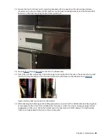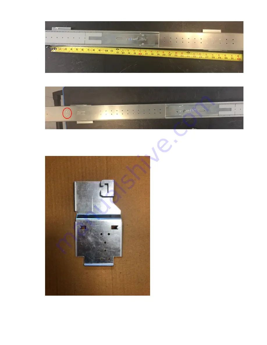
6. Take the right outer rail subassembly in hand, and flip it over (rotate it 180º along its longitudinal
axis).
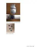
Attachment holes for Step No.7 are identified above.
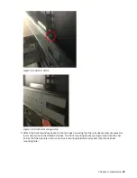
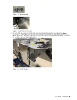
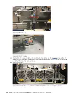
7. Using the quantity-4 panhead screws provided with the CMA kit, attach the CMA attachment bracket
to the rear end of the outer slide, on its outside surface. The following images show the progression
of steps from top to bottom.
Figure 27. CMA attachment
34 IBM ESS expansion: Hardware Installation and Maintenance Guide - Model 106
Summary of Contents for 106
Page 6: ...Russia Electromagnetic Interference Class A Statement 100 Homologation statement 100 vi...
Page 12: ...xii...
Page 18: ...xviii IBM ESS expansion Hardware Installation and Maintenance Guide Model 106...
Page 20: ...2 IBM ESS expansion Hardware Installation and Maintenance Guide Model 106...
Page 44: ...26 IBM ESS expansion Hardware Installation and Maintenance Guide Model 106...
Page 84: ...66 IBM ESS expansion Hardware Installation and Maintenance Guide Model 106...
Page 100: ...82 IBM ESS expansion Hardware Installation and Maintenance Guide Model 106...
Page 108: ...90 IBM ESS expansion Hardware Installation and Maintenance Guide Model 106...
Page 119: ......
Page 120: ...IBM SC27921101...

