Chapter 5. Operation
Before you begin
Before powering on the enclosure system, ensure that all the modules are firmly seated in their correct
slots.
Verify that you have successfully completed the sequential “Installation Checklist” instructions in Table 4
on page 27. Once you have completed these steps, use ESS deployment tools (
gssutils
) to complete
the system setup.
Powering on/powering off
CAUTION: Do not operate the enclosure system until the ambient temperature is within the
specified operating range described in “Environmental requirements” on page 84. If the drive
modules have been recently installed, make sure they have had time to adjust to the
environmental conditions before they are used with production data for I/O.
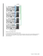
1. Power on the system by connecting the power cables from the PSU to the PDU. See Figure 59 on page
52.
The System Power LED on the front panel should be lit green when the enclosure power is activated.
2. Power the system down by disconnecting the power cord from the power supply module.
When powering up, make sure to power up the enclosures and associated data host in the following
order:
• Drive enclosures first
This ensures that the disks in the drive enclosure have enough time to completely spin up before being
scanned by the controller modules within the controller enclosure.
While enclosures power up, their LEDs blink. After the LEDs stop blinking—if no LEDs on the front, back
and top of the enclosure are amber—the power-on sequence is complete, and no faults have been
detected.
– See Overview of front panel LEDs and Figure 12 on page 15.
– See Overview of rear panel LEDs and figures/tables for rear panel CRUs.
– See Overview of top panel LEDs and figures/tables for top panel CRUs.
• Controller enclosure next if an RBOD is used. Not applicable to server attached JBOD configuration.
Depending upon the number and type of disks in the system, it may take several minutes for the system
to become ready.
• Data host last (if powered down for maintenance purposes).
Note: When powering off, you will reverse the order of steps used for powering on.
• Important: If main power is lost for any reason, upon restoration of power, the Enclosure will restart
automatically.
• Note: See “Front panel LEDs” on page 56 for details pertaining to front panel LEDs and related fault
conditions.
• Important: To avoid potential equipment damage during transport and subsequent loss of data, see
`Procedure: Transporting a 5U expansion enclosure. The procedure describes what to do for the
following situations:
©
Copyright IBM Corp. 2018, 2020
53
Summary of Contents for 106
Page 6: ...Russia Electromagnetic Interference Class A Statement 100 Homologation statement 100 vi...
Page 12: ...xii...
Page 18: ...xviii IBM ESS expansion Hardware Installation and Maintenance Guide Model 106...
Page 20: ...2 IBM ESS expansion Hardware Installation and Maintenance Guide Model 106...
Page 44: ...26 IBM ESS expansion Hardware Installation and Maintenance Guide Model 106...
Page 84: ...66 IBM ESS expansion Hardware Installation and Maintenance Guide Model 106...
Page 100: ...82 IBM ESS expansion Hardware Installation and Maintenance Guide Model 106...
Page 108: ...90 IBM ESS expansion Hardware Installation and Maintenance Guide Model 106...
Page 119: ......
Page 120: ...IBM SC27921101...

