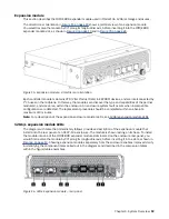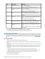
IOM/EBOD expander module
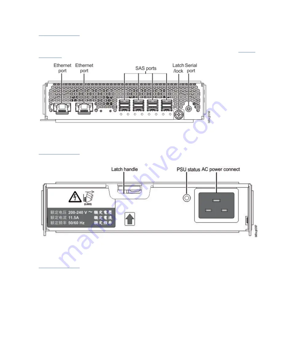
Figure 6 on page 11 shows the IOM/EBOD expander module used in either IOM/EBOD expander module
slot located on the enclosure rear panel. The module is shown resting on its base. To install the module
into one of the IOM/EBOD expander module slots located on the enclosure rear panel, you would first
Figure 6. IOM/EBOD expander module detail
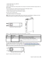
Power supply unit
Figure 7 on page 11 shows the power supply unit used in a Model 106 enclosure. The example shows a
PSU oriented for use in either PSU slot located on the enclosure rear panel.
Figure 7. Power supply unit (PSU) module detail
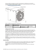
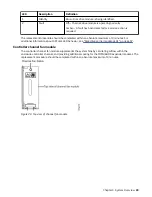
System fan module
Figure 8 on page 12 shows a system fan used in a Model 106 enclosure. The example shows a system
fan module oriented for use in any of the system fan slots located on the enclosure rear panel.
Chapter 3. System Overview 11
Summary of Contents for 106
Page 6: ...Russia Electromagnetic Interference Class A Statement 100 Homologation statement 100 vi...
Page 12: ...xii...
Page 18: ...xviii IBM ESS expansion Hardware Installation and Maintenance Guide Model 106...
Page 20: ...2 IBM ESS expansion Hardware Installation and Maintenance Guide Model 106...
Page 44: ...26 IBM ESS expansion Hardware Installation and Maintenance Guide Model 106...
Page 84: ...66 IBM ESS expansion Hardware Installation and Maintenance Guide Model 106...
Page 100: ...82 IBM ESS expansion Hardware Installation and Maintenance Guide Model 106...
Page 108: ...90 IBM ESS expansion Hardware Installation and Maintenance Guide Model 106...
Page 119: ......
Page 120: ...IBM SC27921101...


