Planning for installation
Before beginning the enclosure installation, familiarize yourself with the system configuration
requirements.
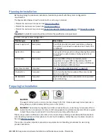
The figures listed below show the locations for each plug-in module:
• Model 106 enclosure front panel: see Figure 3 on page 9
• Model 106 enclosure rear panel: see Figure 4 on page 10
• Model 106 enclosure top panel: see Figure 9 on page 12, Figure 10 on page 13, and Figure 11 on page
Important: Installation work should be performed by qualified service personnel.
Table 5. Storage system configuration
Module type
Location
Description
Power supply unit
Rear panel
Two PSUs provide full power redundancy, allowing
the system to continue to operate while a faulty PSU
is replaced.
System fan
Rear panel
Four system fans provide cooling, allowing the system
to continue to operate while a faulty system fan is
replaced.
I/O module
Rear panel
Up to two IOMs of the same model type are
supported. In single-IOM configurations, the IOM
must be installed in IOM slot No.0 and an IOM blank
must be installed in IOM slot No.1.
Disk drive module
Top panel
See “Populating disk drive slots” on page 13
Channel fan
Top panel
Up to two channel fan modules of the same model
type are supported.
HS Expander
Top panel
Eight removable hot swap expanders are supported:
one 12-drive bay.
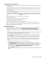
Preparing for installation
CAUTION:
The weight of this part or unit is more than 55 kg (121.2 lb). It takes specially trained persons, a
lifting device, or both to safely lift this part or unit. (C011)
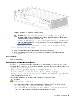
CAUTION: The enclosure—together will all its component parts—is too heavy to manually lift and
install into the rack cabinet. A minimum of three people and a suitable mechanical lift are required
to hoist the enclosure and install it into the rail kit assembly within the rack.
Make sure you wear an effective anti-static wrist or ankle strap and obey conventional ESD precautions
when touching modules and components. Do not touch midplane, motherboard, or module connectors.
See also ESD precautions.
This section provides important preparation requirements and handling procedures for use during
product installation.
28 IBM ESS expansion: Hardware Installation and Maintenance Guide - Model 106
Summary of Contents for 106
Page 6: ...Russia Electromagnetic Interference Class A Statement 100 Homologation statement 100 vi...
Page 12: ...xii...
Page 18: ...xviii IBM ESS expansion Hardware Installation and Maintenance Guide Model 106...
Page 20: ...2 IBM ESS expansion Hardware Installation and Maintenance Guide Model 106...
Page 44: ...26 IBM ESS expansion Hardware Installation and Maintenance Guide Model 106...
Page 84: ...66 IBM ESS expansion Hardware Installation and Maintenance Guide Model 106...
Page 100: ...82 IBM ESS expansion Hardware Installation and Maintenance Guide Model 106...
Page 108: ...90 IBM ESS expansion Hardware Installation and Maintenance Guide Model 106...
Page 119: ......
Page 120: ...IBM SC27921101...


