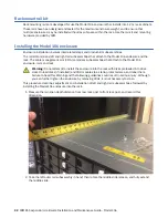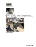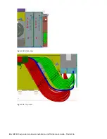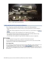
Figure 44. Panhead screws
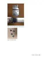
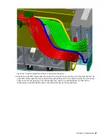
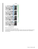
Figure 45. Installed on 4U chassis
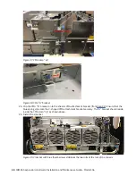
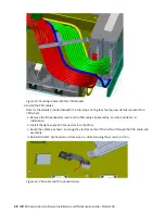
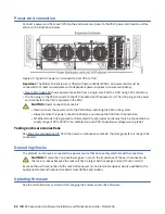
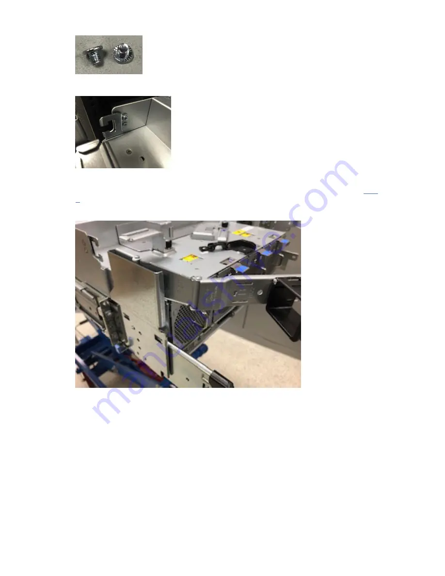
23. Clip the CMA “B” bracket onto the right rail subassembly CMA attachment bracket (from step
7).Ensure that the blue spring clips onto the C-shaped CMA attachment bracket securely, and the
arrow next to the “B” mark on the CMA arm is pointed upward. The "B" bracket should reside outside
of the CMA ramp "lip" (see middle photo).
Figure 46. CMA “B” bracket
Chapter 4. Installation 43
Summary of Contents for 106
Page 6: ...Russia Electromagnetic Interference Class A Statement 100 Homologation statement 100 vi...
Page 12: ...xii...
Page 18: ...xviii IBM ESS expansion Hardware Installation and Maintenance Guide Model 106...
Page 20: ...2 IBM ESS expansion Hardware Installation and Maintenance Guide Model 106...
Page 44: ...26 IBM ESS expansion Hardware Installation and Maintenance Guide Model 106...
Page 84: ...66 IBM ESS expansion Hardware Installation and Maintenance Guide Model 106...
Page 100: ...82 IBM ESS expansion Hardware Installation and Maintenance Guide Model 106...
Page 108: ...90 IBM ESS expansion Hardware Installation and Maintenance Guide Model 106...
Page 119: ......
Page 120: ...IBM SC27921101...

