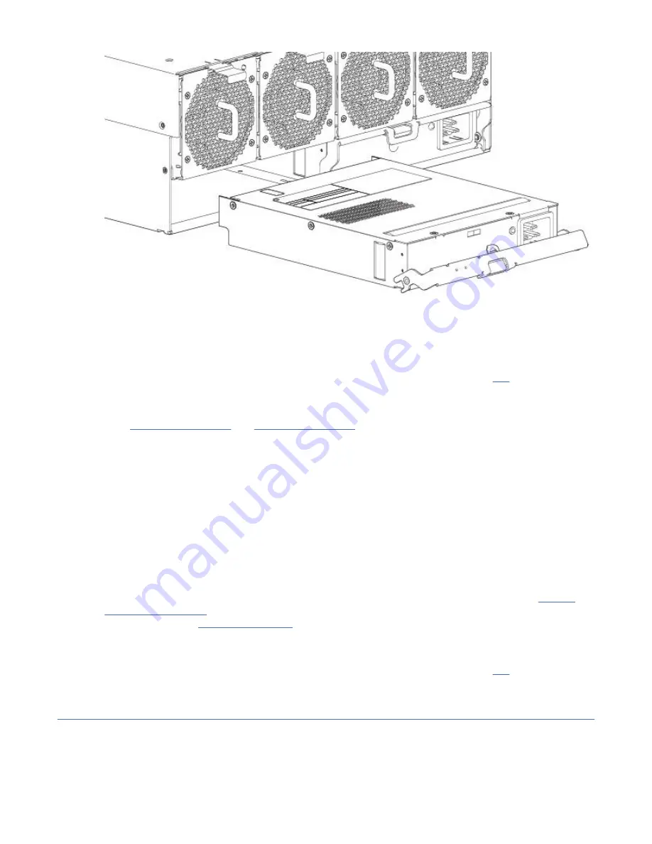
Figure 62. Removing a PSU (2 of 2)
Note: The remove PSU illustrations show a single-core module with single power connection. The
procedure applies equally to single-core and dual-core PSUs used in Model 106 enclosures.
9. If replacing two PSUs, repeat steps 5 through 8, being mindful of the illustrations TIP.
Installing a PSU module
Refer to Figure 61 on page 69 and Figure 62 on page 70 when performing this procedure, but ignore the
directional arrow—since you will insert the module into the slot—rather than remove it.
Important: Handle the PSU carefully, and avoid damaging the connector pins. Do not install the PSU if
any pins appear to be bent.
1. Check for damage, especially to all module connectors.
2. With the PSU handle in the open position, slide the module into the enclosure, taking care to support
the base and weight of the module with both hands.
3. Lever the module home by manually closing the PSU handle. You should hear a click as the latch
handle engages and secures the PSU to its connector on the back of the power midplane.
4. Connect the power cable to the power source and the PSU.
Power cables are typically routed to the PSU from the cable management arm (CMA). Verify that the
180º power cable bends lie flat in the CMA baskets. Route the cables as shown in step 3 of Routing
cables using the CMA, ensuring they lay flat on the CMA shelf and through the PSU cable clips
assembly. See also Figure 4 on page 10.
5. Verify that the bitonal PSU Status LED is on/Green. Verify that cooling fans are spinning with no fail
states. Verify that the front panel LED states show no amber module faults.
6. If replacing two PSUs, repeat steps 1 through 5, being mindful of the illustrations TIP.
Replacing a system fan module
This section provides procedures for replacing a failed system fan module. Within this CRU module, if one
of the two internal rotors fails, then a fault occurs, indicating module failure. Illustrations in system fan
replacement procedures show rear panel views of the enclosure, with the fan properly oriented for
insertion into the rear panel of the enclosure.
70 IBM ESS expansion: Hardware Installation and Maintenance Guide - Model 106
Summary of Contents for 106
Page 6: ...Russia Electromagnetic Interference Class A Statement 100 Homologation statement 100 vi...
Page 12: ...xii...
Page 18: ...xviii IBM ESS expansion Hardware Installation and Maintenance Guide Model 106...
Page 20: ...2 IBM ESS expansion Hardware Installation and Maintenance Guide Model 106...
Page 44: ...26 IBM ESS expansion Hardware Installation and Maintenance Guide Model 106...
Page 84: ...66 IBM ESS expansion Hardware Installation and Maintenance Guide Model 106...
Page 100: ...82 IBM ESS expansion Hardware Installation and Maintenance Guide Model 106...
Page 108: ...90 IBM ESS expansion Hardware Installation and Maintenance Guide Model 106...
Page 119: ......
Page 120: ...IBM SC27921101...


