background image

Summary of Contents for 1402

Page 1: ......

Page 2: ...ce ts t 7 l Department _________________ If this manual is misplaced it should be returned to the above address frl CjD o l I 7 d E Customer Engineering Instruction Reference 1402 Card Read Punch 1960...

Page 3: ...Clutch Drive Installation 2 4 FILE FEED 2 5 Principles of Operation 2 5 Clutch Adjustments 2 6 Clutch Removal 2 6 Service Checks 2 7 Joggler Adjustments 2 7 HOPPER AND PICKER KNIVES 2 7 Principles of...

Page 4: ...14 4 14 4 14 4 14 4 14 4 15 4 15 4 15 4 15 4 15 4 16 4 16 4 17 5 1 5 1 5 1 5 1 5 1 5 1 5 1 5 1 5 3 5 3 5 3 5 3 5 3 5 4 5 4 5 4 6 1 6 1 6 1 6 1 6 2 6 3 6 3 6 3 6 3 6 4 6 4 6 5 SERVICE AIDS 7 1 CUSTOMER...

Page 5: ...ffiM 1402 Card Read Punch...

Page 6: ...ds and check card punchingat a maximum speed of 250 cards per minute Cards are placed in the 1200 card ca pacity hopper 12 edge first face down Card feeding is illustrated in the feed schematic diagra...

Page 7: ...re the stop occurs Non Process Runout Read Switch Used to run cards out of the read feed The last two cards run out will not be processed The read hopper must be empty to make this switch effective No...

Page 8: ...ft Interlock This switch provides the same function as the magazine interlock whenthe lowering frame is lowered Crank Interlock This is a manually operated switch which must be turned off to insert th...

Page 9: ......

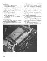
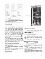
Page 10: ...i CHIP BOX tlI PMT PUNCH MAGNET TERMINALS HD RELAYS AND MAIN CONTACTOR _ _ J BEHI ND FUSE PANEL BRUSH IMPULSE TRANSISTORS REAR OF RELAY GATE Figure 2 1 1402 Front View Adjust the motor pulley to feed...

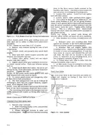
Page 11: ...o engage the ratchet and rotate the mechanism that drives the feed knives and controlled feed rolls Unless the clutch magnet is again impulsed the clutch will disengage when the opposite end of the ar...

Page 12: ...ssembly shaft Figure B SEE NOTE ADJUST SCREWS FOR 020 TO 022 CLEARANCE HERE _ l CHECK 001 TO 003 CLEARANCE HERE NOTE 008 to 012 UNLATCHING CLEARANCE SHOULD GIVE 75 OR MORE LATCH SURFACE CONTACT LOCATI...

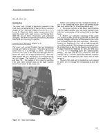
Page 13: ...fclutch shaft 5 Loosen retaining clamp and remove clamp and file feed drive pulley together 6 Remove clutch pulley drive belt 7 Remove clutch pulley assembly It may be necessary to loosen V belt input...

Page 14: ...timings o 0 a Clutch engagement time 315 1 b Brush impulse CB timing c RC CB timing d RL CB timing TIMER INDEX SHAFT MAGNET ASSEMBLY FILE FEED Principle of Operation Figure 2 7 The file feed consists...

Page 15: ...of either cards or card weight The card weight is designed to pass through the lower magazine into the hopper and must be used to feed the last cards The front joggler interlock mounted under the read...

Page 16: ...e 2 10 Undertheseconditions there should be 003 to 010 clearance betweenthe cards and the lower end of the jogglingsurfaces the lower end of the joggling surfaces is in line with the top of the card f...

Page 17: ...adjustedand should never be changed Each picker knife block is fixed on its arm ITwo carballoy pieces are inserted in the block surface to resist wear The inserts are ground to specifications for knif...

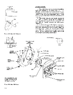
Page 18: ...aligns witg a o s o ra p a h NOTE This is just a referenoe point for making brush timings When the brushes are onthe soribed line refer to Brush Assembly Adjustment retime the pioker knife oamshaft to...

Page 19: ...EWS Figure 2 13 Brush Assembly 2 10 f If clearance is incorrect remove assembly and shift separator in proper direction 2 Loosen locking screws at either end of brush assembly and shift block so that...

Page 20: ...e scribed line settings listed above 2 Dynamically time the brushes as per wiring diagram by shifting the picker knife timing Do not accomplish brush timings by shifting brushes off scribed line NOTE...

Page 21: ......

Page 22: ...bar consists of a spring steel t PUNCH FEED SELECT MAGNETS COIL II COIL strip located just above the normal card line Any card that is bentenough to flex the metal strip causes a switch to operate Th...

Page 23: ...t and at the junction of the jam bar and jam bar lever Figure 3 4 2 The tape must be adjusted so that the switch will be operated with a tape deflectionofl 16 STACKERS Principles of Operation Figure 3...

Page 24: ...h hub identified by a red dot for 003 to 005 clearance while its spring sleeve is flush against the mating hub HUB IDENTIFIED WITH RED HELICAL MATI NG HUB CARD ALIGNMENT LEVER 4 6 CARDS ECCENTRIC TO J...

Page 25: ...RD GUIDES CAN BE A CAUSE OF EXCESSIVE CARD JAMMING TO ELIMINATE THIS AS A CAUSE FORM THESE GUIDES TO MATCH THE ILLUSTRA TED PROFILE DO NOT DISTORT THIS PROFI LE TO ACCOMPLISH REINSTALLATION IF MOUNTIN...

Page 26: ...need to be filtered out by PLCB s NOTE The synchronous tooth 3150 of the clutch must be used when checking card transport timings USing ga nuzs ber 608 83 otherwise all timings will be 90 180 or 270 o...

Page 27: ...EDGE OF DOG CARRIER AND LATCH ARM SHOULD LINE UP AT 3150 F LATCH ARM ADJUSTING C I_ Figure 4 2 Punch Clutch Clearances c...

Page 28: ...eneva operates on the same principle 4 ihe genevas in other high speed punches Thisgeneva however is comparatively simple It consists of a driVe disc with two pins to drive two geneva discs There is o...

Page 29: ...gage clutch and turn to 1850 c Turn cam on shaft until feed knives hold cttrd snug against first feed rolls d Tighten cam on shaft 4 4 CARD GUIDES There are four card guides that must be kept in prope...

Page 30: ...ed rolls are cammed open Whenthe first intermitted feed rolls open the feeding of the card through the punch station is under control of the second intermittent feed rolls The opening and closing of t...

Page 31: ...ntermittent feed roll is in time Second Intermittent Feed Roll and Second Stepped Feed Roll 1 Trip clutch at 3000 and continue turning o machine until clutch engages 315 2 Crank machine to 2900 3 Inse...

Page 32: ...heck must be made prior to alignment 7 When feeding cards held against the r ight hopper side plate check the right side aligner surface for 005 minimum clearance to a card when a card is fed into the...

Page 33: ...at 300 0 and turn machine to 294 0 3 Loosen split hub of pulley located on rear end of second stepped feed roll 4 While keeping machine at 294 0 turn second stepped roll by hand and feed a card lengt...

Page 34: ...s up through bottom of bed plate b Forward aligners are mounted to this up right and will come out with it First Stepped Feed Roll Removal 1 Remove side aligners 2 Remove four screws two at each end t...

Page 35: ...2 to 030 card clearance between upper and lower guides MAGNET UNIT Figure 4 10 Punch Unit 4 10 ROLL OPENING DEVICE Principles of Operation Figure 4 8 The two stepped rolls the two lower intermittent r...

Page 36: ...er assembly consist of 1 A punch bail and two sets of cam follower arms 2 An interposer setup bail and two sets of cam follower arms The punch magnet unit consists of 80 magnets latches interposer lin...

Page 37: ...terposer is free to be restored by springtension On the return stroke of the punch bail the punch is positively restored by the punch bail Punch Unit Removal 1 Remove the die 2 Remove brush block asse...

Page 38: ...g holes in the cams with the hole in the punch unit left side frame 0 2 Set the punch index at 0 Interposer SetupBailAdjustment Figure 4 11 1 Remove punch unit from machine 2 Remove punch magnetunit f...

Page 39: ...from top to bottom CAUTION Do not remove top bar with other three bars removed 4 14 2 After inspection replace bar assembly 4 and then 3 3 Remove magnet bar assembly 1 4 Replace magnetbar assembly 2a...

Page 40: ...the punch magnet controlling the position to be removed This will increase the latch travel 5 Unhook interposer link from its latch 6 Remove interposer and interposer link 7 Assemble in reverse order...

Page 41: ...Figure 4 17 Punch Unit Adjusting Screws 4 16 a Loosen four holding screws ontopofpunch unit Figure 4 17 b Loosen locknut on horizontal adjusting screw and turn adjusting screw in proper direc tion to...

Page 42: ...ex does not read 0 o 0 120 or 240 proceed as follows 1 Loosen split hub of punch unit inputpulley 2 Depress geneva timing pin and turn machine manually until pin seats in geneva drive disk 3 While hol...

Page 43: ......

Page 44: ...ler belt 3 and slipit ofi 3 Install drive motor belt and tighten 4 Install CR idler belt 3 line up reference marks and tighten with idler pulley 3 CR Idler Belt 1 If there is sufficient clearance to w...

Page 45: ...STEPPED FEED ROLL DRI VE BELT DARKENED BELTS ARE UNDER CONTROL OF PUNCH FEED CLUTCH Figure 5 2 Punch Feed Timing Belts 0 1 TI MER INDEX MOTOR PULLEY 0 0 PACB UNIT DRI VE TO TRANSPORT MECHAN ISM 0 CR I...

Page 46: ...shaft lines to line up with the scr d o lines on the casting set the punch index on 0 en slip the PACB belt over the punch pulley If c e is taken the PACB unit can be tightened and both ts will be in...

Page 47: ...s retain the mounting plate to the three spacer studs mounted in the machine side frame Carefully remove solar cell unit and allow it to swingout of working area 2 Loosen idler pulley Install belt and...

Page 48: ...as the digit impulse RLCB s did prior to the solar cell Figure 6 1 Solar Cell Position Before proceeding into the timing procedure or any of the adjustment steps there are several points that may ass...

Page 49: ...cated on the relay gate transistor panel Final duration adjustment should be made after one hour of power on 2 With power removed and reader cranked to 9 time a coarse timing can be obtained by loosen...

Page 50: ...ress the end of the contact strap to re lieve pressure which will permit rotating and or reseating lamp It may be necessary in some cases to reposition lamp holder after rotation as in step 4 Solar Ce...

Page 51: ...figuration before installing Figure 6 7 5 Install new contact wires one ata time to avoid twisting N or 8 N O Vi I e 0 N e 19 I N e Amootur Normal Atmatur AlIrOCled Figure 6 6 PM Schematic 6 4 6 Re as...

Page 52: ...sembly must be replaced stoning or cleaning of any of these cam contact surfaces is not practical as the results do not justify the time and expense involved Certain positions of the RLCB s and PACB s...

Page 53: ......

Page 54: ...g is displayed onthe read feed index Read Brush Display This momentary contact switch is used in conjunction with the brush selection switch to display read feed brush timing Cam Selection This rotary...

Page 55: ......

Page 56: ...ver contact should make when the card lever is 060 003 above the sur face of the feed knives Pressure to operate the lever should be 18 to 24 grams Pocket Selectors Figure 8 1 1 Adjust the air gap of...

Page 57: ...O ELIMINATE THIS AS A CAUSE FORM THESE GUIDES TO MATCH THE ILLUSTRA TED PROFILE DO NOT DISTORT THIS PROFILE TO ACCOMPLISH REINSTALLATION IF MOUNTING SCREW HOLES DO NOT ALIGN ELONGATE THE UPPER MOUNTIN...

Page 58: ...r minute read print operation is that the print buffer feature must be installed in the printer In order to get a 600 card per minute feed on the 1402 a 6 tooth ratchet clutch assembly is used With th...

Page 59: ......

Page 60: ...hen position 6 while ob serving the timer index A bouncing card lever will show up as a spot of light between 1580 and 1880 Readjust card lever contacts Reader Check Lights 1 This may occur as a resul...

Page 61: ...hey have not become polished at a point where they contact the card 6 Varying vertical registration canbe causedby intermittent roll closing too soon and moving card 9 2 slightly at the end of the pre...

Page 62: ...oll hanger pivots all clutch pivots 9 Lubricate gears aligner cams feed roll opening cams picker knife cams punch clutch latch cam extension spring ends punch clutch armature latch pivot 17 Lubricate...

Page 63: ...e stripper cavity latch spring hooks armature pivots setup bail channel cam surfaces with 17 Lubricate needle bearing grease fittings die locating studs with 20 Fill drive motor oil cups with 9 Replac...

Page 64: ...pplies in the 1401 3 HDl2 in the 1401 picks when the 6 v and 30 v are available and supplies the rest of the relays with 20 v HD15 also picks with HD12 if required 4 2B HD3 picks when the 12 v is avai...

Page 65: ...cuit exists from T2 conducting 0 volts commonbrush contact roll read brush and the respective row bit core to 11 2 20 v This furnishes the other 1 2 write current to the proper core refer to 1401 manu...

Page 66: ...r to start and continue to run 1 lOB R28 is picked when punch motor stops 2 lOA Cards in hopper will pick R21 3 6A DU2 is picked by the load or start key 4 lOB R29 and HD2 are picked through inter loc...

Page 67: ...tus 5 5B The check reset key will pick DU4 through R28 3T and R7 3N 6 llA The DU4 BL point opens the holdto R31 11 4 and turns off the punch stop light 7 llA The DU4 AL point conditions the U Read Che...

Page 68: ...primary 208 or 230 volt power up sequence relays are not located in the 1402 Model 2 The voltage comes into the machine from another unit Instead of the master CB pulses RLCB going directly to the po...

Page 69: ......

Page 70: ......

Reviews: