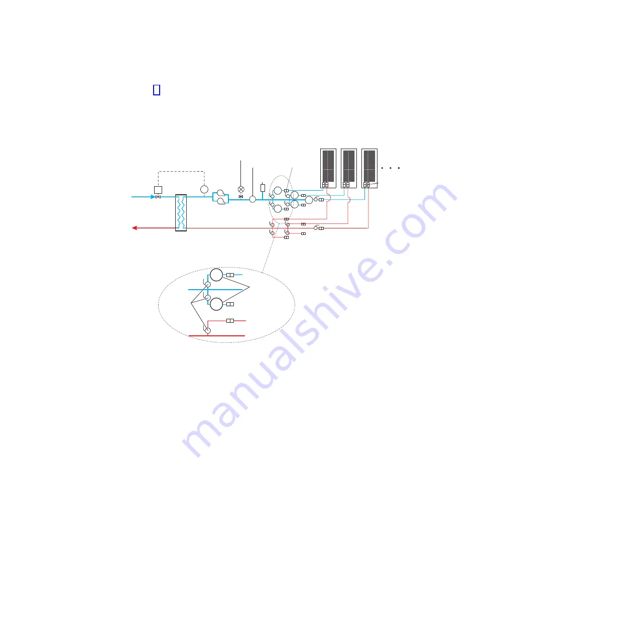
Figure 6 shows an example of a facilities fabricated solution. The actual number of
heat exchangers that are connected to a secondary loop depends on the capacity
of the coolant distribution unit that is running the secondary loop.
Building
chilled
water
Flow
control
valve
Rear door
heat exchangers
s
T
Return
Redundant
pumps
Distribution
manifolds
Flexible hoses,
maximum length
15.24 meters (50 feet)
Loop heat
exchanger
Supply
CS
CS
CS
CS
CS
Secondary side
temperature feedback
for controlled water
temperature to
specification
Return
Supply
CS
CS
Shutoff
valves
Circuit setter
flow control
valves
Pressure relief
valve (based on
maximum
pressure
application)
Expansion
tank
Optional low
impedance
quick-connect
coupling
Quick-connect
couplings
Flowmeter
FM
Figure 6. Coolant distribution unit that uses a fabricated facilities solution
Chapter 2. Heat exchanger planning, specifications, and requirements
17
Summary of Contents for 1756
Page 1: ...Rear Door Heat eXchanger V2 Type 1756 Installation and Maintenance Guide ...
Page 2: ......
Page 3: ...Rear Door Heat eXchanger V2 Type 1756 Installation and Maintenance Guide ...
Page 38: ...28 Rear Door Heat eXchanger V2 Installation and Maintenance Guide ...
Page 64: ...54 Rear Door Heat eXchanger V2 Installation and Maintenance Guide ...
Page 90: ...80 Rear Door Heat eXchanger V2 Installation and Maintenance Guide ...
Page 98: ...88 Rear Door Heat eXchanger V2 Installation and Maintenance Guide ...
Page 101: ...website continued support line telephone numbers 79 Index 91 ...
Page 102: ...92 Rear Door Heat eXchanger V2 Installation and Maintenance Guide ...
Page 103: ......
Page 104: ... Part Number 00D2434 Printed in USA 1P P N 00D2434 ...


