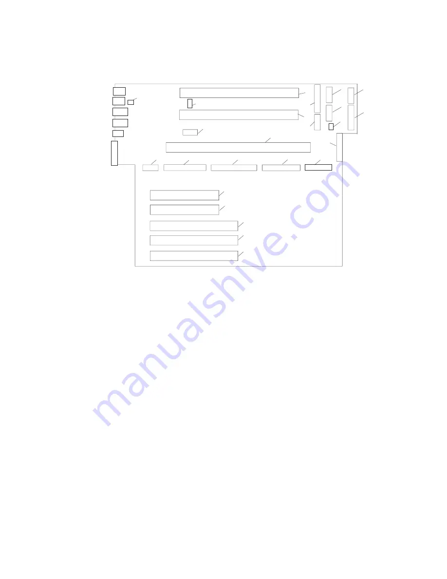
System Board Locations
2
3
6
4
5
8
9
10
11
12
13
14
17
15
18
16
19
20
21
22
23
24
7
1
1
Rear serial port (#1) connector
2
Rear power and attention LED connector
3
Processor power connector
4
Processor #2 card connector
5
Processor #1 card connector
6
Power connector
7
Power connector
8
Power connector
9
Power connector
10
Light path card connector
11
Processor fans
12
Blowers
13
Diskette connector
14
Memory card connector
15
Front serial port connector
16
Operator panel connector
17
CD-ROM IDE connector
18
Internal SCSI connector
19 - 20
32-bit PCI connectors
(33MHz, 5V)
21
64-bit PCI connector
(33MHz, 5V)
22 - 23
64-bit PCI connector
(50MHz, 3.3V)
24
Battery connector
Chapter 1. Reference Information
5
Summary of Contents for 265
Page 1: ...IntelliStation POWER 9112 Model 265 Service Guide SA38 0609 00 IBM...
Page 2: ......
Page 3: ...IntelliStation POWER 9112 Model 265 Service Guide SA38 0609 00 IBM...
Page 14: ...xii Service Guide...
Page 20: ...Fan Locations 1 2 3 4 1 Fan 1 2 Fan 2 3 Fan 3 4 Fan 4 4 Service Guide...
Page 46: ...30 Service Guide...
Page 96: ...80 Service Guide...
Page 190: ...174 Service Guide...
Page 287: ...Replacement Replace in reverse order Chapter 9 Removal and Replacement Procedures 271...
Page 308: ...292 Service Guide...
Page 324: ...308 Service Guide...
Page 328: ...312 Service Guide...
Page 354: ...338 Service Guide...
Page 363: ......
Page 364: ...IBM Printed in U S A February 2002 SA38 0609 00...
Page 365: ...Spine information IBM IntelliStation POWER 9112 Model 265 Service Guide SA38 0609 00...


