Processor and Memory Card Cover
The following procedures cover removal and replacement of the processor and memory
card cover.
Removal
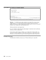
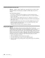
1. If you have not already done so, shut down the system as described in “Stopping
the System” on page 248.
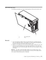
2. If you have not already done so, remove the service access cover as described in
“Service Access Cover” on page 251.
3. Record any memory card or processor LEDs that are on.
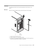
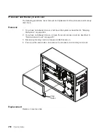
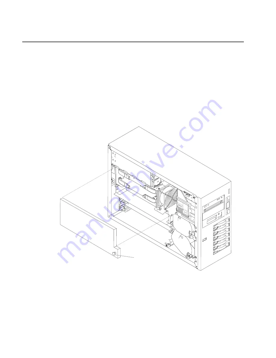
4. Pull out on the snap button, and remove the processor and memory card cover.
Snap
Button
Replacement
Replace in reverse order.
254
Service Guide
Summary of Contents for 265
Page 1: ...IntelliStation POWER 9112 Model 265 Service Guide SA38 0609 00 IBM...
Page 2: ......
Page 3: ...IntelliStation POWER 9112 Model 265 Service Guide SA38 0609 00 IBM...
Page 14: ...xii Service Guide...
Page 20: ...Fan Locations 1 2 3 4 1 Fan 1 2 Fan 2 3 Fan 3 4 Fan 4 4 Service Guide...
Page 46: ...30 Service Guide...
Page 96: ...80 Service Guide...
Page 190: ...174 Service Guide...
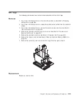
Page 287: ...Replacement Replace in reverse order Chapter 9 Removal and Replacement Procedures 271...
Page 308: ...292 Service Guide...
Page 324: ...308 Service Guide...
Page 328: ...312 Service Guide...
Page 354: ...338 Service Guide...
Page 363: ......
Page 364: ...IBM Printed in U S A February 2002 SA38 0609 00...
Page 365: ...Spine information IBM IntelliStation POWER 9112 Model 265 Service Guide SA38 0609 00...

