Replacement
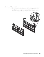
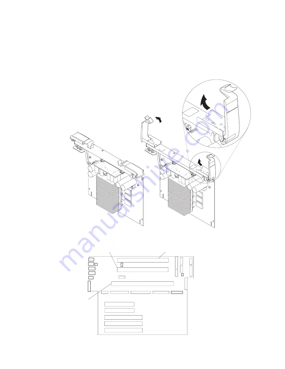
1. Open the retention latches.
Both retention latches should be in an upright position.
See the following illustration.
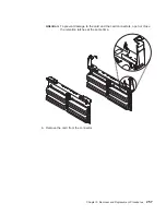
Attention: To prevent damage to the card and to the card connectors, open or
close both retention latches at the same time.
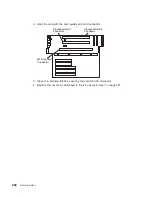
2. Align the card with the card guides and card connector.
Processor Card 1
Connector
Memory Card
Connector
Processor Card 2
Connector
264
Service Guide
Summary of Contents for 265
Page 1: ...IntelliStation POWER 9112 Model 265 Service Guide SA38 0609 00 IBM...
Page 2: ......
Page 3: ...IntelliStation POWER 9112 Model 265 Service Guide SA38 0609 00 IBM...
Page 14: ...xii Service Guide...
Page 20: ...Fan Locations 1 2 3 4 1 Fan 1 2 Fan 2 3 Fan 3 4 Fan 4 4 Service Guide...
Page 46: ...30 Service Guide...
Page 96: ...80 Service Guide...
Page 190: ...174 Service Guide...
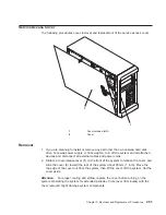
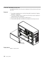
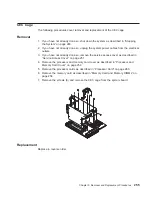
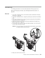
Page 287: ...Replacement Replace in reverse order Chapter 9 Removal and Replacement Procedures 271...
Page 308: ...292 Service Guide...
Page 324: ...308 Service Guide...
Page 328: ...312 Service Guide...
Page 354: ...338 Service Guide...
Page 363: ......
Page 364: ...IBM Printed in U S A February 2002 SA38 0609 00...
Page 365: ...Spine information IBM IntelliStation POWER 9112 Model 265 Service Guide SA38 0609 00...


