4.
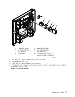
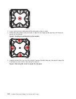
Remove
the
cover
from
the
new
MCM
module.
See
Figure
4.
MCM
module
alignment
5.
Each
time
an
MCM
module
(or
pass-through)
is
installed
on
the
system
board,
the
associated
interposer
must
be
inspected.
Inspect
the
MCM
interposer,
using
the
magnifying
glass
provided
in
the
system
toolkit.
The
interposer
is
not
acceptable
and
the
module
must
be
returned
if
the
following
conditions
occur:
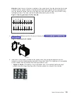
v
Figure
5.
Shorts:
If
the
button,
a
loop
of
the
button
wire,
or
an
individual
button
wire
lead
extends
more
than
three
times
the
width
of
the
wire
outside
of
a
connector
hole
chamfer
(top
side)
or
counter
bore
pin
indent
(bottom
side).
Analyze
hardware
problems
109
Summary of Contents for 270
Page 2: ......
Page 12: ...x Hardware Remove and Replace Part Locations and Listings...
Page 279: ...Figure 3 CCIN 2881 with pluggable DIMM Analyze hardware problems 267...
Page 281: ...Figure 6 Models 830 SB2 with FC 9074 HSL and SPCN locations Analyze hardware problems 269...
Page 283: ...Figure 1b Model 840 SB3 processor tower dual line cord Analyze hardware problems 271...
Page 294: ...01 gif port and LED locations 282 Hardware Remove and Replace Part Locations and Listings...
Page 295: ...s src rzaq4519 gif locations Analyze hardware problems 283...
Page 483: ...Table 1 Cover assembly FC 5095 Expansion I O Tower Analyze hardware problems 471...
Page 614: ...602 Hardware Remove and Replace Part Locations and Listings...
Page 618: ...606 Hardware Remove and Replace Part Locations and Listings...
Page 621: ......
Page 622: ...Printed in USA SY44 5917 02...


