background image

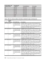
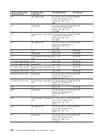
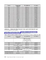
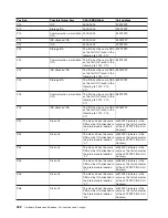
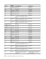
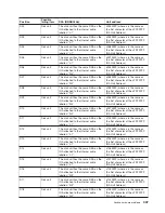
Position


Possible


failing


component


DSA


(BBBBCcbb)


Unit


address


D18


Disk


unit


The


disk


unit


has


the


same


DSA


as


the


IOA


attached


to


the


internal


cable


labelled


R-2

.


x10500FF


(where


x


is


the


same


as


the


first


character


of


the


xFFFFFFF


IOA


Unit


Address)


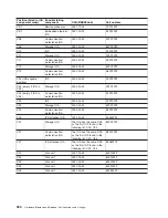
D19


Disk


unit


The


disk


unit


has


the


same


DSA


as


the


IOA


attached


to


the


internal


cable


labelled


R-2

.


x10600FF


(where


x


is


the


same


as


the


first


character


of


the


xFFFFFFF


IOA


Unit


Address)


D20


Disk


unit


The


disk


unit


has


the


same


DSA


as


the


IOA


attached


to


the


internal


cable


labelled


R-2

.


x10700FF


(where


x


is


the


same


as


the


first


character


of


the


xFFFFFFF


IOA


Unit


Address)


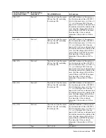
D21


Disk


unit


The


disk


unit


has


the


same


DSA


as


the


IOA


attached


to


the


internal


cable


labelled


L-1

.


x20300FF


(where


x


is


the


same


as


the


first


character


of


the


xFFFFFFF


IOA


Unit


Address)


D22


Disk


unit


The


disk


unit


has


the


same


DSA


as


the


IOA


attached


to


the


internal


cable


labelled


L-1

.


x20400FF


(where


x


is


the


same


as


the


first


character


of


the


xFFFFFFF


IOA


Unit


Address)


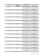
D23


Disk


unit


The


disk


unit


has


the


same


DSA


as


the


IOA


attached


to


the


internal


cable


labelled


L-1

.


x20500FF


(where


x


is


the


same


as


the


first


character


of


the


xFFFFFFF


IOA


Unit


Address)


D24


Disk


unit


The


disk


unit


has


the


same


DSA


as


the


IOA


attached


to


the


internal


cable


labelled


L-1

.


x20600FF


(where


x


is


the


same


as


the


first


character


of


the


xFFFFFFF


IOA


Unit


Address)


D25


Disk


unit


The


disk


unit


has


the


same


DSA


as


the


IOA


attached


to


the


internal


cable


labelled


L-1

.


x20700FF


(where


x


is


the


same


as


the


first


character


of


the


xFFFFFFF


IOA


Unit


Address)


D26


Disk


unit


The


disk


unit


has


the


same


DSA


as


the


IOA


attached


to


the


internal


cable


labelled


R-2

.


x20300FF


(where


x


is


the


same


as


the


first


character


of


the


xFFFFFFF


IOA


Unit


Address)


D27


Disk


unit


The


disk


unit


has


the


same


DSA


as


the


IOA


attached


to


the


internal


cable


labelled


R-2

.


x20400FF


(where


x


is


the


same


as


the


first


character


of


the


xFFFFFFF


IOA


Unit


Address)


D28


Disk


unit


The


disk


unit


has


the


same


DSA


as


the


IOA


attached


to


the


internal


cable


labelled


R-2

.


x20500FF


(where


x


is


the


same


as


the


first


character


of


the


xFFFFFFF


IOA


Unit


Address)


D29


Disk


unit


The


disk


unit


has


the


same


DSA


as


the


IOA


attached


to


the


internal


cable


labelled


R-2

.


x20600FF


(where


x


is


the


same


as


the


first


character


of


the


xFFFFFFF


IOA


Unit


Address)


D30


Disk


unit


The


disk


unit


has


the


same


DSA


as


the


IOA


attached


to


the


internal


cable


labelled


R-2

.


x20700FF


(where


x


is


the


same


as


the


first


character


of


the


xFFFFFFF


IOA


Unit


Address)


Analyze


hardware


problems


335

Summary of Contents for 270

Page 1: ...iSeries iSeries Server 270 800 810 820 825 830 840 870 890 SB2 and SB3 Hardware Remove and Replace Part Locations and Listings Version 5 Release 2 SY44 5917 02 ERserver...

Page 2: ......

Page 3: ...iSeries iSeries Server 270 800 810 820 825 830 840 870 890 SB2 and SB3 Hardware Remove and Replace Part Locations and Listings Version 5 Release 2 SY44 5917 02 ERserver...

Page 4: ...603 Third Edition August 2002 This edition applies only to reduced instruction set computer RISC systems Copyright International Business Machines Corporation 1998 2002 All rights reserved US Governm...

Page 5: ...and 810 Time of day TOD battery 16 Model 820 remove and replace procedures 16 Model 820 Air moving device AMD B01 through B04 17 Model 820 Cards concurrent 18 Model 820 Cards dedicated 19 Model 820 C...

Page 6: ...tower with non dual line cords AC box A01 74 Models 840 SB3 Processor Tower with dual line cords AC box A01 A03 concurrent maintenance 74 Model 830 with FC 9074 Model 840 with FC 9079 or FC 8079 with...

Page 7: ...rd AC charger A01 137 FC 5074 FC 5079 FC 9079 with dual line cord AC module A01 and A02 137 FC 5074 FC 5079 FC 9074 FC 9079 Air moving device B01 and B02 137 FC 5074 FC 5079 FC 9079 Batteries T01 T02...

Page 8: ...595 Air moving device B01 B02 B03 and B04 191 FC 5095 FC 0595 Cards concurrent 192 FC 5095 FC 0595 Cards dedicated 193 FC 5095 FC 0595 Covers 194 FC 5095 FC 0595 Device board DB1 and DB2 194 FC 5095 F...

Page 9: ...25 Addresses Model 820 327 Addresses Model 825 329 Addresses Models 830 SB2 System Unit with FC 9074 Base I O Tower 332 Addresses Models 840 SB3 Processor Tower and FC 9079 Base I O Tower 336 Addresse...

Page 10: ...19 Type model and part number list 520 Hardware part number information 520 Power related part number information 533 Internal and external cables 535 Cleaning testing and miscellaneous parts 537 Data...

Page 11: ...ed protection 581 Find the load source disks on systems with mirrored protection 581 Alternate IPL device 581 Reclaim IOP cache storage 583 Forms 583 Problem summary form 584 Preventive maintenance PM...

Page 12: ...x Hardware Remove and Replace Part Locations and Listings...

Page 13: ...or point to additional isolation procedures if available System reference codes SRCs can appear on the control panel the Product Activity Log PAL the Main Storage Dump Manager display or on various d...

Page 14: ...ep the system up and running 3 Find the FRU you are removing in this section and follow the procedures 4 When you have completed the remove procedure install the FRU by reversing the remove procedure...

Page 15: ...he Models 270 800 and 810 may be housed in a FC 0551 frame The upper and lower system units are placed on rails in the frame If you are working on the upper or lower unit follow these instructions and...

Page 16: ...artition that owns the resource If the resource is not owned follow the procedure from the primary partition For all Model 270 and 810 cards v For the Model 270 the processor feature code must be 22A7...

Page 17: ...If the LED is blinking multiple times per second rapidly or it is off then the card is powered off 8 Remove the left side cover See Models 270 800 and 810 Covers 9 Remove and label any cables connect...

Page 18: ...cord 3 Remove the left side cover See Models 270 800 and 810 Covers 4 Are you removing a memory DIMM v Yes Press down on the latches that are located on each side of the memory DIMM to release it fro...

Page 19: ...270 800 and 810 b Reinstall the control panel card by reversing the procedure to this point c Go to Verify the repair This ends the procedure v No Disconnect the cables that are attached to the backsi...

Page 20: ...Remove the screws holding the front of the disk unit cage assembly to the front of the system unit frame 7 Remove the screws from the back inside of the cage assembly 8 Pull the cage forward about on...

Page 21: ...of the display concurrent maintenance is not available v If the Logical Resources Associated with a Packaging Resource display appears with at least one Device Services entry concurrent maintenance is...

Page 22: ...Ensure that the device does not contact the backplane at this time e Press Enter on the console After the delay time the light above the device location will begin flashing You now have nine seconds...

Page 23: ...ted maintenance 1 Determine if the system has logical partitions Go to Determine if the system has logical partitions before continuing with this procedure 2 Were you directed here from Recovery proce...

Page 24: ...ow these instructions and access the internal parts by opening the front cover and sliding the system unit out on its rails To remove or replace memory A through H 1 Power off the system See Power on...

Page 25: ...remove or replace the power supply P02 on Models 270 800 and 810 The Models 270 800 and 810 may be housed in an FC 0551 frame The upper and lower system units are placed on rails in the frame If you...

Page 26: ...expansion attached disconnect both the system line cord and the expansion unit line cord 3 Remove the left side cover See Models 270 800 and 810 Covers 4 Press on the little locking tabs until process...

Page 27: ...n unit line cord 3 Remove the left side cover See Models 270 800 and 810 Covers 4 Remove the PCI cards See Models 270 800 and 810 Cards dedicated Note the locations to aid in replacing them correctly...

Page 28: ...the frame If you are working on the upper or lower unit follow these instructions and access the internal parts by opening the front cover and sliding the system unit out on its rails CAUTION This pro...

Page 29: ...ir moving device B01 B02 B03 and B04 concurrently The configuration of three power supplies and four AMDs must be installed to use this procedure Use the dedicated procedure below with less than four...

Page 30: ...as instructed by local regulations RSFTC234 Attention All cards are sensitive to electrostatic discharge see Work with electrostatic discharge sensitive parts Attention If removing the cover while po...

Page 31: ...m02 storage ibm com disk ess documentation html This ends the procedure Model 820 Cards dedicated For use by authorized service providers Use this procedure to remove or replace cards dedicated in the...

Page 32: ...ew ones in place Note the position and orientation of each card See Control panel Model 820 b Reinstall the control panel card by reversing the procedure to this point c Go to Verify the repair This e...

Page 33: ...e Model 820 Covers 4 Remove the EMC shield in front of the disk units by pulling out on the side two latches 5 Remove the disk units from the disk unit cage Label the position of each disk unit 6 Remo...

Page 34: ...h the two surfaces of the latching mechanism together and rotate the handle of the disk unit towards you Pull the disk unit partially out of the tower The light above the device location will go off a...

Page 35: ...el 820 Disk unit dedicated For use by authorized service providers Use this procedure to remove or replace the disk unit dedicated in the Model 820 Attention The disk unit is sensitive to electrostati...

Page 36: ...slot and rotate the handle towards the disk unit to latch it into the slot e Replace the covers that were removed during this procedure and return to the procedure that sent you here This ends the pr...

Page 37: ...e power supply all the way in and then lifting the handle to lock into place This ends the procedure Model 820 Processor M03 For use by authorized service providers Use this procedure to remove or rep...

Page 38: ...r on off the system and logical partitions on page 561 2 Pull the power plug in the rear of the system 3 Remove the front cover See Model 820 Covers on page 21 4 Partially remove the unit by pulling o...

Page 39: ...e screws holding the SPCN connector plate to the rear of the frame Pull out the plate j The screws that mount the boards and stiffener to the frame 4 Remove the system unit backplane the power distrib...

Page 40: ...0793 will be displayed Press Enter 0793 00 will be displayed 11 After a few seconds the display will go blank and then the bring up SRCs will be displayed When the panel returns to function 01 bring u...

Page 41: ...r set the time and date This ends the procedure Model 825 remove and replace procedures For use by authorized service providers Model 825 Air moving device AMD B01 B02 concurrent Model 825 Cards concu...

Page 42: ...e and replace procedures If you use concurrent maintenance on a partitioned system follow the procedures from the partition that owns the resource If the resource is not owned follow the procedure fro...

Page 43: ...above the card slot If the LED is blinking multiple times per second rapidly or it is off then the card is powered off 8 Remove the left side cover See Model 825 Covers 9 Remove and label any cables...

Page 44: ...move the cover b Open the latches on the identified processor and remove the processor c If you are replacing the processor label the memory DIMM locations so that they can be reinstalled in the same...

Page 45: ...and enter it on this screen Note DST SST options to activate POD will not be visible if the system password has been bypassed d If you are replacing a processor capacity card that was associated with...

Page 46: ...h button located on the back of the control panel directly behind the keystick position for 3 4 seconds 14 After exchanging an item go to Verify the repair This ends the procedure Model 825 Covers For...

Page 47: ...e system unit frame 7 Remove the screws from the back inside of the cage assembly Important The SCSI cable is located on the left side of the cage assembly 8 Remove the air flow shield from the left s...

Page 48: ...u Pull the disk unit partially out The light above the device location will go off and remain off as soon as the device is no longer making contact with the backplane Attention If you remove the devic...

Page 49: ...d f Replace the covers that were removed during this procedure and return to the procedure that sent you here This ends the procedure Model 825 Disk unit dedicated For use by authorized service provid...

Page 50: ...y into the slot and rotate the handle towards the disk unit to latch it into the slot e Replace the covers that were removed during this procedure and return to the procedure that sent you here This e...

Page 51: ...ed 7 Remove the six screws retaining MB2 8 Remove MB2 from the frame 9 Reverse this procedure to install the card This ends the procedure Model 825 Interlock switch For use by authorized service provi...

Page 52: ...ocessor card cage cover 6 Remove the processor card or cards 7 Remove the processor card cage Figure 2 Processor card cage and PCI tailstock support bracket 40 Hardware Remove and Replace Part Locatio...

Page 53: ...odel 825 Cards dedicated procedure Model 825 Power cable harness assembly For use by authorized service providers Use this procedure to remove and install the power cable harness assembly on the Model...

Page 54: ...ssembly AMD connector from the inner frame wall by squeezing the tabs located on the connector 14 Remove the four screws from the power cable retaining bracket located on the right side of the system...

Page 55: ...oval v If you need to remove optical media go to Optical media manual removal 2 In some cases you do not need to power down the system to change a removable media unit Are you removing a unit by using...

Page 56: ...the unit from the system frame If the unit is DVD RAM and manual removal of optical media is required go to Optical media manual removal 6 To replace a new unit perform the following a Select Device C...

Page 57: ...em unit backplane CB1 and the Power bus bar assembly if necessary 1 Power off the system See Power on off the system and logical partitions 2 Unplug the power cord from the back of the system unit On...

Page 58: ...the disk unit cages control panel function cables and the cables running to the rear bulk head located on the left side of the system 7 Remove the plastic PCI card separators 8 Remove the integrated...

Page 59: ...9 Remove the processor card cage and PCI tailstock support bracket Figure 3 Processor card cage and PCI tailstock support bracket Analyze hardware problems 47...

Page 60: ...screws near the power supply connectors in the right rear of the system See Figure 3 in Final assembly Model 825 b Replace the power bus bar assembly Then continue with the next step 14 Install the n...

Page 61: ...To avoid possible explosion do not burn exchange or charge the battery Discard the battery as instructed by local regulations for lithium batteries RSFTC232 To remove or replace the time of day batte...

Page 62: ...ear and perform the following steps a Remove the power cords from the AC input charger b Remove the top and bottom screws that hold the AC input charger to the frame c Pull the AC input charger out of...

Page 63: ...emoval procedure After exchanging an item go to Verify the repair This ends the procedure Models 830 SB2 with FC 9074 Battery T01 through T04 For use by authorized service providers Use this procedure...

Page 64: ...830 SB2 with FC 9074 Cards dedicated For Models 830 SB2 base I O tower cards FC 9074 except IXS cards v Card positions C01 through C07 and C09 through C15 permit concurrent maintenance using HSM You c...

Page 65: ...t to remove d Turn the latch counter clockwise and lift up on the black latch to release the card Attention If you are removing a FC 2890 then you must use dedicated maintenance e Remove the card by g...

Page 66: ...el 830 SB2 system unit processor drawer Continue with the next step 4 You are removing a card in the Model 830 SB2 system unit processor drawer using dedicated maintenance Refer to Final assembly rear...

Page 67: ...r replacing memory DIMMS refer to the Figure 3 CCIN 2881 with pluggable DIMM See page 267 in the Locations Model 830 topic for DIMM locations f Unlatch the DIMMs from the memory riser card by pressing...

Page 68: ...this time It is important for this area to be clean and free of debris prior to continuing with the next step of this procedure e Loosen and remove the 3 8 9 5mm hex head screw spring assembly from th...

Page 69: ...es of the processor module assembly and the system backplane assembly meet Be careful not to brush over the contact surface again Then continue brushing around and away from the perimeter of the conta...

Page 70: ...e the card Note If you are removing a FC 2890 then remove the screws from the tail stock and slide the card cage forward about 6 inches then the FC 2890 can be removed or inserted h Remove the card by...

Page 71: ...rm the following steps 1 Grasp the top right corner of the cover and pull it towards you to open it 2 Tilt the top of the cover away from the tower and lift the cover off This ends the procedure To re...

Page 72: ...screws that hold the disk unit cage assembly in to the frame d Remove the two retaining screws that are located inside of the disk unit cage assembly the top right and bottom left corners e Remove th...

Page 73: ...Remove the screws that hold the PCI card enclosure in the frame d Pull the PCI card enclosure partially out of the frame while lifting the cables clear of the enclosure e Press the release mechanism...

Page 74: ...parts 1 Were you directed here from Recovery procedures v Yes Continue with the next step v No Go to Recovery procedures Then return here 2 After you have determined the location of the disk unit to...

Page 75: ...v No Continue with the next step v Yes Replace the covers that were removed during this procedure and return to the procedure that sent you here This ends the procedure 3 To install a disk unit using...

Page 76: ...off the system See Power on off the system and logical partitions b Disconnect the power cord c Put the disk unit part way into the desired slot and rotate the handle of the disk unit towards you d P...

Page 77: ...replace only that card and not the panel Are you replacing the processor capacity card v Yes Continue with the next step v No If you are replacing the interactive card continue with step 18 See page...

Page 78: ...power distribution board PB1 in an Models 830 SB2 with FC 9074 To remove or replace the power distribution board PB1 1 You must remove both disk unit backplanes DB1 and DB2 before continuing with thi...

Page 79: ...e frame 10 Pull the power distribution backplane slightly towards you and lift it up to remove it from the frame 11 Install the power distribution backplane by reversing the removal procedure After ex...

Page 80: ...ow to determine the CCIN and location for the processor cards 3 Use the CCIN in conjunction with the Type model and part number list on page 520 to obtain the part numbers for the processors that you...

Page 81: ...DVD RAM unit go to Optical media manual removal This ends the procedure 4 Before exchanging a removable media unit you must ensure that the unit is not in use and is varied off Note If you are removin...

Page 82: ...step v Yes After exchanging an item go to Verify the repair This ends the replace procedure 5 Attempt the device concurrent maintenance procedure again without physically moving the unit Did the light...

Page 83: ...dart 19 Rotate the lever handles that hold the processors in place to the closed downward position and separate the sheet metal cage from the backplane by lifting it up and off of the board 20 Instal...

Page 84: ...card enclosure Press the surfaces of the two latching mechanisms together and tilt the top of the cover away from the frame to remove it c Remove the cables from the top of the PCI cards and note the...

Page 85: ...Models 840 SB3 remove and replace procedures For use by authorized service providers Models 840 SB3 processor tower with non dual line cords AC box A01 Models 840 SB3 processor tower with dual line c...

Page 86: ...A03 1 Swing open the lower rear cover See Model 840 SB3 Covers Perform the following steps from the rear of the system 2 Disconnect the ac power cord for the AC box that you are working on 3 Remove th...

Page 87: ...ove or replace the concurrent maintenance adapter card A02 on a Model 840 SB3 processor tower To remove or replace the concurrent maintenance adapter card A02 1 Power down the system This is no longer...

Page 88: ...attery CAUTION The weight of this part or unit is between 18 and 32 kilograms 39 7 and 70 5 pounds It takes two persons to safely lift this part or unit RSFTC204 CAUTION The battery is a lead acid bat...

Page 89: ...electrostatic discharge sensitive parts To remove or replace cards concurrently 1 From the Hardware Service Manager display select Packaging hardware resources 2 Select Hardware contained in packagin...

Page 90: ...g detail on the 2766 or 2787 IOA Logical Hardware Resource information in Hardware Service Manager in SST or DST The 16 digit World Wide Port Name can also be determined by appending the digits 1000 t...

Page 91: ...osure Press the two latching mechanisms together and tilt the top of the cover away from the frame to remove it See Final assembly rear Models 840 and SB3 processor tower c Remove the mounting screws...

Page 92: ...5294 FC 9079 FC 9094 Covers Attention If removing the cover while powered on errors may occur due to Electromagnetic Interference To remove the front and rear covers 1 Lift up on the cover 2 Pull the...

Page 93: ...u used to remove the card Then go to step 7 See page 81 6 Perform the following to finish removing the panel a Remove the cables from the panel b Remove the four screws on the front bezel and remove t...

Page 94: ...orm the following Figure 1 System unit control panel with keystick NB1 a Apply ac power b Insert the new keystick into the control panel The control panel will display 0000 5553 c Locate the push butt...

Page 95: ...No Perform Dedicated maintenance Remove and replace See page below v Yes Perform Concurrent maintenance Remove and replace See page below Concurrent maintenance Remove and replace Attention If removin...

Page 96: ...ce does not contact the backplane at this time e Press Enter on the console After the delay time the light above the device location will begin flashing You now have nine seconds to insert the disk un...

Page 97: ...or SB3 1 Look to see if the panel backlight is on to verify that ac power is applied 2 If the system is either powered off or running on battery power you must apply ac power to the AC module before c...

Page 98: ...the rear AMDs g Remove the CEC regulator EMC access plate that covers the power regulators h Mark the regulators and their locations so that you can reinstall them in the proper locations i Remove the...

Page 99: ...by reversing the procedure The new power supply will automatically power on when it is installed Note To return the panel to normal display scroll to 07 and press Enter 7 After exchanging an item go...

Page 100: ...Figure 1 Internal removable media locations 6 Perform the following a Select System Service Tools SST If you cannot get to SST select DST Do not perform a system IPL to get to DST b Select Start a Ser...

Page 101: ...nue with the next step v Yes After exchanging an item go to Verify the repair This ends the install procedure 3 There is a power problem One of the following is the problem v The new unit is defective...

Page 102: ...emove the I O tower panel cable from the right EMC bracket f Remove the EMC brackets first the top bracket then the left and right from around the front cage g Mark the processor memory regulator and...

Page 103: ...n top h Remove the backplane from front cage i Close all of the connector latches on the new Backplane The latches need to be closed so they do not interfere with the rear cage when it is installed 8...

Page 104: ...d A02 Models 870 and 890 FC 9094 with dual line cord AC module A01 and A02 Models 870 and 890 FC 9094 Air moving device B01 and B02 Models 870 and 890 Bulk power controller BPC Models 870 and 890 Bulk...

Page 105: ...controller BPC on the Models 870 and 890 The BPC is located immediately above the top bulk power regulator BPR See Locations Models 870 and 890 To remove the bulk power controller BPC 1 Do not power d...

Page 106: ...ced by decoding the SRC see System reference codes or see Locations Models 870 and 890 3 Open the cover to access the field replaceable unit FRU See Models 870 and 890 Covers on page 97 4 Note the sta...

Page 107: ...the BPE out of the frame Note The BPE weighs less than 40 pounds To replace the bulk power enclosure BPE 1 Slide the board enclosure FRU the BPE into the frame until the BPE side flanges make contact...

Page 108: ...to the down position and plug the cable to the BPC ensuring plug location 5 To indicate completion of these steps press the white Service Complete button on the UEPO panel This ends the procedure Mode...

Page 109: ...or blank to be removed 4 Loosen the upper and lower fasteners using the torque tool P N 6422789 alternating between the fasteners until the unit can slide out of the slot 5 Grasp both sides of the cap...

Page 110: ...ized service providers Use this procedure to remove or replace the DC converter assembly DCA on the Models 870 and 890 The following safety notice applies to power related field replaceable units FRUs...

Page 111: ...k the torque on both thumb screws 6 Plug all the cables into the DCA ensuring correspondence of plug locations and cable labeling 7 To indicate completion of these steps press the white Service Comple...

Page 112: ...ure See Models 870 and 890 MSA air mover enclosure 3 Perform a general cleaning operation using a sash brush part number 450732 not the one included with the FRU kit and vacuum cleaner to remove any a...

Page 113: ...sleeves off the posts 9 Use a disposable lint free cloth to clean the sleeves 10 Pull the L3 module straight back off the posts and place it with the LGA connector down in the four position tray from...

Page 114: ...the assembly inside the carton 5 Seal the carton and ship To install L3 modules 1 Go to the Testing L3 cache modules for a short circuit See page 128 page and install the L3 module short circuit test...

Page 115: ...e 4 Remove the protective cover from the new L3 module See Model 890 L3 modules remove the protective cover Figure 4 Installing the L3 module 5 Each time an L3 module is installed on the system board...

Page 116: ...moved earlier with the new sleeves provided with the L3 module kit If you are reseating an existing module use a lint free cloth to wipe any dust off the sleeves that you removed earlier Attention Be...

Page 117: ...e L3 module 12 Replace the primary Network interface controller NIC card 13 Replace the MSA air mover enclosure See Models 870 and 890 MSA air mover enclosure 14 Plug in the power cord and power on th...

Page 118: ...over that attaches utilizing only the cam locks To remove MCM and pass through modules Attention If more than one module is to be replaced or reseated begin with the topmost module replace it and then...

Page 119: ...dule 10 Move the actuation bolt to the up position and hand tighten to hold the assembly in the up position 11 At the front hold the MCM module with one hand while using the 8mm socket to unlatch the...

Page 120: ...ssor subsystem Hold the vacuum hose near the brush to remove any debris the brush generates 3 Follow the procedure described in the Attention note below to clean the LGA site using the brush supplied...

Page 121: ...be inspected Inspect the MCM interposer using the magnifying glass provided in the system toolkit The interposer is not acceptable and the module must be returned if the following conditions occur v...

Page 122: ...module 9 Push the actuation bolt in and slide the spring plate assembly to the down position 10 Use the torque wrench supplied with the system tool kit to tighten the actuation bolt When the wrench c...

Page 123: ...ork interface controller NIC card 15 Replace the DCA books and blanks that you removed earlier See Models 870 and 890 DC converter assembly DCA 16 Replace the MSA air mover enclosure See Models 870 an...

Page 124: ...Grasp the release latches located at the top and bottom of the memory book between your thumb and index finger press the tabs together Pivot the tabs and pull the book straight back 5 Reverse this pro...

Page 125: ...g replaced remove all VPD cards from the old primary NIC card and install them into the new primary NIC card See Models 870 and 890 VPD card Inspect the Network interface controller NIC card You must...

Page 126: ...f 6 Verify that all the cables are labeled for plug location and then unplug the cables from the MDA on the MSA to be removed 7 If the FRU call listed both the MSA and MDA for removal it is synonymous...

Page 127: ...ocedure below 1 With the front cover open locate the right frame extender located on the opposite side of the UEPO switch The 50 mm about 2 inches wide label should be installed vertically along the e...

Page 128: ...y loosen the two thumb screws ensuring that both screws are completely loose from the module base before proceeding Figure 2 Loosen the thumb screws 116 Hardware Remove and Replace Part Locations and...

Page 129: ...owing a Place the module on the ESD mat b Place your thumb over one of the release latches and your forefinger over the opposite latch Note To ensure proper grip your thumb and finger should be direct...

Page 130: ...c Squeeze the latches and at the same time pull the cover from the interposer Figure 4 Pulling the cover from the interposer 118 Hardware Remove and Replace Part Locations and Listings...

Page 131: ...w these procedures can cause interposer damage 1 Place the module on an ESD mat with protective cover facing up 2 Manually loosen the actuation screw located in the middle of the spring place using a...

Page 132: ...ngs with the posts present on the module Figure 2 Rotating the spring plate on the module 5 Carefully remove the cover from the module to expose the LGA interposer Be careful to keep the cover level a...

Page 133: ...caution not to damage the interposer This ends the procedure Models 870 and 890 Remove and replace tools For use by authorized service providers Use the table below to obtain part numbers for tools n...

Page 134: ...74 1 Velcro roll 08J5557 1 Wheel chocks 44P0144 Tailgate assembly 09P2481 Rack lift tool 11P4369 Lift place assembly tool Models 870 and 890 Shorts test qualified service meters and fail criteria For...

Page 135: ...50 Fluke 70 2 320 0 20 0 50 Fluke 70 3 320 0 20 0 50 Fluke 73 320 0 20 0 50 Fluke 73 2 320 0 20 0 50 Fluke 73 3 320 0 20 0 50 Fluke 75 320 0 20 0 50 Fluke 75 2 320 0 20 0 50 Fluke 75 3 320 0 20 0 50 F...

Page 136: ...automated shorts tester There are three procedures that are covered in this topic v Testing for proper operation of LGA ST and LGA ST battery See page 124 v Testing MCM and passthru modules for a sho...

Page 137: ...e 5 Install an MCM passthru module 6 Press the Rocker switch forward to the MCM L3 PWR GND position This checks the MCM passthru for power to ground shorts It also checks the L3s for power to ground s...

Page 138: ...s a short between the two L3 power domains Perform the following a Remove the L3 and inspect the interposer for shorts b Reinstall the L3 once and repeat the test If the fail persists replace the L3 8...

Page 139: ...the meter COM to the Capacitor book TP 5 RTN Then continue with MCM installation shorts test procedure 2 See page 127 v If you are using the short circuit test option perform the following Connect th...

Page 140: ...personnel Ensure the UEPO switch is in the Off position before performing this procedure 1 Power down the system See Power on off the system and logical partitions 2 Ensure the UEPO is off 3 Disengage...

Page 141: ...ect the L3 cache module install another L3 cache module M03 M04 M09 M10 M12 M13 M05 M06 M22 M23 M28 M29 M26 M27 M19 M20 Then go to step 2 See page 129 7 Are all the memory and network interface contro...

Page 142: ...Then go to step 2 See page 129 L3 cache shorts test procedure 4 1 Choose from the following options v If you are using the new capacitor card option Connect the meter V to Capacitor book TP 3 L3 L an...

Page 143: ...replace the system clock card Note Be sure to align the guide feature on the card with the guide feature on the system board 1 Squeeze the tabs on the clock card and push it straight in 2 Replace the...

Page 144: ...along with their location at the front and rear of the system 5 Unplug all power cables from the line power source Attention Because this procedure is performed with power removed from the system ref...

Page 145: ...ully move the lift tool with the system unit backplane to the staging area The brake and wheel chocks must be in place when transferring the system unit backplane chassis to or from the packaging mate...

Page 146: ...screws then slide it back and tighten the screws 3 Install the external cable if required to connector J2 number 7 in figure 1 v If the external EPO connection is installed the internal toggle switch...

Page 147: ...card Note The VPD cards are located in the primary network interface controller NIC card 1 Remove the primary NIC card See the Models 870 and 890 Network interface controller NIC card remove and repla...

Page 148: ...IPL is performed to ensure the POD activation code has been saved Attention The POD activation code or codes must be entered within 48 hours or an SRC A6XX 47XX will be posted in the panel requiring a...

Page 149: ...A01 and A02 1 Do not power down the tower if it is powered on this procedure can be done concurrently 2 Open the rear cover See FC 5074 FC 5079 FC 5094 FC 5294 FC 9079 FC 9094 Covers 3 Refer to Locat...

Page 150: ...wer Remove the battery power unit by performing the following CAUTION Be careful when removing or installing this part or unit This part or unit is heavy but has a weight smaller than 18 kilograms 39...

Page 151: ...rtition you cannot power down the domain v If the resource is the console IOA or the console IOP for a secondary partition then power down the secondary partition and follow the procedure from the pri...

Page 152: ...Note If you have exchanged a 2766 or 2787 Fibre Channel IOA the IBM 2105 disk unit subsystem must be updated to use the World Wide Port Name of the new 2766 or 2787 IOA This name can be found in the...

Page 153: ...The 16 digit World Wide Port Name can also be determined by appending the digits 1000 to the beginning of the 12 digit IEEE Address found on the tailstock label of the Fibre Channel IOA Use the ESS We...

Page 154: ...5079 FC 9079 Device board DB1 and DB2 For use by authorized service providers Use this procedure to remove or replace the device board DB1 and DB2 in an FC 5074 FC 5079 or FC 9079 142 Hardware Remove...

Page 155: ...arge sensitive parts c Remove the screws that hold the disk unit cage assembly to the frame d Remove the two retaining screws that are located inside of the disk unit cage assembly the top right and b...

Page 156: ...the frame while lifting the cables clear of the enclosure e Press the release mechanism that is located along the top right side of the enclosure and carefully slide the enclosure towards you Make sur...

Page 157: ...rmine if the system has logical partitions before continuing with this procedure 2 Were you directed here from the Recovery procedures topic v No Go to Recovery procedures on page 539 v Yes After you...

Page 158: ...re that the device does not make contact with the backplane at this time e Press Enter on the console After the delay time the light above the device location will begin flashing You now have 9 second...

Page 159: ...y procedures v Yes After you have determined the location of the disk unit to replace remove the front covers for access See FC 5074 FC 5079 FC 5094 FC 5294 FC 9079 FC 9094 Covers 3 Remove the EMC acc...

Page 160: ...two side fasteners to release the display panel assembly 5 Slide the panel partially out of the frame 6 Disconnect the cables that are attached to the backside of the display panel 7 Remove the displ...

Page 161: ...r batteries see FC 5074 FC 5079 FC 9079 Batteries T01 T02 T03 and T04 3 Remove the screws from the power subframe assembly 4 From the front of the tower reach through the frame and remove the cables f...

Page 162: ...to a power source RSFTD010 6 Remove the power supply from the frame 7 Install the power supply by reversing the removal procedure After exchanging an item go to Verify the repair Note Do not slam the...

Page 163: ...tape unit see Tape cartridge Manual removal 2 If you need to remove optical media from and optical device go to Optical media Manual removal This ends the procedure 4 Before exchanging a removable med...

Page 164: ...main off for a few seconds when the device contacts the backplane Then it should go on and remain on Did the light on the device go on and remain on v No Continue with the next step v Yes After exchan...

Page 165: ...losure towards you Make sure that the cables are clear of the enclosure 5 Remove the PCI cards from the enclosure and note their locations See FC 5074 FC 5079 FC 5094 or FC 5294 Cards dedicated 6 Inst...

Page 166: ...r 07A9 00 will be displayed e Use the arrow keys to increment decrement to the frame address nn nn is usually 02 03 and so forth for expansion towers 07nn will be displayed Press Enter 07nn 00 will be...

Page 167: ...e by authorized service providers Use this procedure to remove or replace the air moving device AMD B01 and B02 in an FC 5075 To remove or replace the air moving device B01 and B02 1 Are there two AMD...

Page 168: ...To avoid the release of lead Pb into the environment do not burn Discard the circuit card as instructed by local regulations RSFTC234 Attention All cards are sensitive to electrostatic discharge see W...

Page 169: ...this procedure to remove or replace the cards dedicated in the FC 5075 In some cases you do not need to power down the system to change PCI cards Use the guidelines in FC 5075 Cards concurrent to det...

Page 170: ...wo side latches 5 Remove the disk units from the disk unit cage Label the position of each disk unit 6 Remove the screws holding the disk unit cage to the frame The screws are located on the front and...

Page 171: ...h the two surfaces of the latching mechanism together and rotate the handle of the disk unit towards you Pull the disk unit partially out of the tower The light above the device location will go off a...

Page 172: ...This ends the procedure FC 5075 Disk unit dedicated For use by authorized service providers Use this procedure to remove or replace the disk unit dedicated in an FC 5075 Attention The disk unit is se...

Page 173: ...e towards the disk unit to latch it into the slot e Replace the covers that were removed during this procedure and return to the procedure that sent you here This ends the procedure FC 5075 Display pa...

Page 174: ...lane by reversing the procedure This ends the procedure FC 5075 Power supply P01 and P02 For use by authorized service providers Use this procedure to remove or replace the power supply P01 and P02 in...

Page 175: ...f Use the arrow keys to increment decrement to a configuration ID to 90 0790 will be displayed Press Enter 0790 00 will be displayed After a few seconds the display on the addressed FC 5075 frame will...

Page 176: ...unit back on See the Expansion unit power procedure 12 After exchanging an item go to Verify the repair This ends the procedure FC 5078 FC 0578 FC 5088 FC 0588 remove and replace procedures For use by...

Page 177: ...remove the cable by pressing down on the cable retainers to eject it 6 Remove the AMD controller card BB1 by pulling out on the latch knob and sliding the card back toward you 7 Install the AMD contro...

Page 178: ...tus of Missing after the description Only one resource will be listed as not missing Select this resource for the concurrent maintenance operation 3 A listing of the power domain is shown Find the IOA...

Page 179: ...u should use dedicated or concurrent remove and replace procedures CAUTION The circuit card contains lead solder To avoid the release of lead Pb into the environment do not burn Discard the circuit ca...

Page 180: ...the cover off Note Refer to Figure 2 Rear cover removal in FC 5074 FC 5079 FC 5094 FC 5294 FC 9079 FC 9094 Covers for details This ends the procedure FC 5078 FC 0578 FC 5088 FC 0588 Display panel NB1...

Page 181: ...Do not power off the system Note Remove and replace only one power supply at a time To remove or replace the power supplies P01 and P02 1 Do not power off the system if it is powered on 2 Open the fr...

Page 182: ...power cord using the Expansion unit power procedure Then return here and continue with step 13c c Select function 07 on the system panel and press Enter 07 will be displayed d Use the arrow keys to i...

Page 183: ...g AC module powered on v Yes Continue with the next step v No Go to step 3 See page 171 2 Is the failing AC module location 2 A02 See Locations and addresses for system or expansion unit you are worki...

Page 184: ...by reversing this procedure Note Do not install power supplies P00 and P01 AC jumper cables on the same AC input module 8 After exchanging an item go to Verify the repair This ends the procedure FC 5...

Page 185: ...console IOP for the system or primary partition you cannot power down the domain v If the resource is the console IOA or the console IOP for a secondary partition then power down the secondary partiti...

Page 186: ...e location to which the resource was last assigned 3 Press Enter The Work with Controlling Resource display will appear 4 Determine the location where you want to assign the resource and select Assign...

Page 187: ...of the new 2766 or 2787 IOA This name can be found in the Port worldwide name field on the iSeries server by displaying detail on the 2766 or 2787 IOA Logical Hardware Resource information in Hardwar...

Page 188: ...ave the original system unit keys and are you reusing them v No Continue with the next step v Yes After exchanging an item go to Verify the repair 8 Perform the following Figure 1 System unit control...

Page 189: ...refer to Figure 1 Front cover removal See page below v To open or remove the rear cover refer to Figure 2 Rear cover removal See page below Perform the following steps to open or remove each cover 1 U...

Page 190: ...e Locations and addresses Press the surfaces of the two latching mechanisms together and tilt the top of the cover away from the frame to remove it b Record the locations of the disk units and then re...

Page 191: ...ng an item go to Verify the repair This ends the procedure FC 5094 FC 9094 Device board DB3 For use by authorized service providers Use this procedure to remove or replace the device board DB3 in an F...

Page 192: ...cable from the rear of the control panel See FC 5074 FC 5079 Control panel NB1 c Unplug the control panel cable from the base DASD board assembly DB3 d Remove the two retaining screws that are located...

Page 193: ...the disk unit that you are removing 4 To remove a disk unit using concurrent maintenance perform the following a Select System Service Tools SST If you cannot get to SST select DST Do not perform a s...

Page 194: ...d remain off for a few seconds when the device contacts the backplane Then it should go on and remain on Attention If you install the device when the light is not flashing data may be lost the disk un...

Page 195: ...the system see Power on off the system and logical partitions b Disconnect the power cord c Put the disk unit part way into the desired slot and rotate the handle of the disk unit towards you d Push t...

Page 196: ...eplace the power distribution backplane 1 You must remove both disk unit backplanes DB1 and DB2 before continuing with this procedure Perform FC 5094 FC 9094 Device boards DB1 and DB2 for each backpla...

Page 197: ...place the Power supply P00 P01 P02 P03 in an FC 5094 or FC 9094 To remove or replace the power supply P00 P01 P02 P03 1 Do not power off the expansion unit if it is powered on this procedure can be pe...

Page 198: ...able media D41 and D42 1 Determine if the system has logical partitions Go to Determine if the system has logical partitions before continuing with this procedure 2 Remove media if any from the device...

Page 199: ...re continuing d Press the Enter key on the console After the delay time the light at the top right of the device will begin flashing You now have 9 seconds to pull out firmly on the handles and pull t...

Page 200: ...tructed by local regulations for lithium batteries RSFTC232 To remove or replace the time of day battery 1 Power off the FC 9094 expansion unit See Power on off the system and logical partitions 2 Rem...

Page 201: ...t hold the PCI card enclosure to the frame e Pull the PCI card enclosure partially out of the frame while lifting the cables clear of the enclosure f Press the release mechanism that is located along...

Page 202: ...ress Enter 07A9 00 will be displayed e Use the arrow keys to increment decrement to the frame address nn nn is usually 02 03 and so forth for expansion towers 07nn will be displayed Press Enter 07nn 0...

Page 203: ...ure to remove or replace the air moving device AMD B01 B02 B03 and B04 in an FC 5095 FC 0595 Four running Air Moving Devices AMDs and two power supplies must be installed and powered on to perform thi...

Page 204: ...FC 5095 FC 0595 Cards dedicated if you choose to perform dedicated card removal CAUTION The circuit card contains lead solder To avoid the release of lead Pb into the environment do not burn Discard t...

Page 205: ...llowing URL http ssddom02 storage ibm com disk ess documentation html This ends the procedure FC 5095 FC 0595 Cards dedicated For use by authorized service providers Use this procedure to remove or re...

Page 206: ...unit 3 Remove the front and right side covers See FC 5095 FC 0595 Covers 4 Remove the EMC shield in front of the disk units by pulling out on the two side latches 5 Remove the disk units from the dis...

Page 207: ...e nine seconds to pinch the two surfaces of the latching mechanism together and rotate the handle of the disk unit towards you Pull the disk unit partially out of the tower The light between the two D...

Page 208: ...otate the handle of the disk unit towards you Then push the disk unit completely into the slot and rotate the handle towards the disk unit to latch it into the slot The light between the two DASD encl...

Page 209: ...rs for access See FC 5095 FC 0595 Covers 4 Remove the EMC access plate that is over the location of the disk unit that you are removing For location information see Locations FC 5095 FC 0595 I O tower...

Page 210: ...to Verify the repair This ends the procedure FC 5095 FC 0595 Power distribution backplane PB1 For use by authorized service providers Use this procedure to remove or replace the power distribution bac...

Page 211: ...ver 5 Remove the PCI cards and the card dividers See FC 5095 FC 0595 Cards dedicated 6 Remove the power supplies 7 Remove the PCI card support brackets headstock and the power supply bracket See Figur...

Page 212: ...a system unit and an expansion unit connect the expansion unit end of the cable first 1 Disconnect the cable at the frame ID card position and port that you are working on 2 Is the connection an opti...

Page 213: ...mponent 1 Check the Service Action Log SAL for the frame number with the failing component 2 Using the xSeries server documentation remove the top cover 3 Check the LED Display in the top left side of...

Page 214: ...sult in the loss of customer data If the system has been powered down PRIOR to the battery service action you MUST IPL to DST and continue this procedure BEFORE replacing the battery The following saf...

Page 215: ...attery This is the minimum amount of time needed for the card to recognize that the battery has been replaced To remove or replace the cache battery pack 1 Is the cache battery pack on a type 2780 or...

Page 216: ...ery unit from the battery casing Save the battery casing The replacement battery pack will not come equipped with a casing Note Ensure that the cache battery pack is disconnected for at least 15 secon...

Page 217: ...and cache directory card for type 2748 2763 and 2778 Figure 2 Cache battery pack and cache directory card for type 2757 Figure 3 Cache battery pack and cache directory card for type 2782 and 5703 Ana...

Page 218: ...Find the resource name of the card you are working with Note The Concurrently Maintainable Battery Pack field should indicate yes If it does not indicate yes then discontinue this procedure and conta...

Page 219: ...e message Cache started on IOA This ends the procedure Separating the removable cache card from the base card on type 2780 cards Attention All cards are sensitive to electrostatic discharge See Workin...

Page 220: ...4 Turn the card over 5 Remove four screws B from the removable cache card as shown 208 Hardware Remove and Replace Part Locations and Listings...

Page 221: ...to begin separating the cards Continue turning the jack screw until you feel the cards separate 7 Separate the base card from the removable cache card Important Turn the jack screw back down fully cl...

Page 222: ...able cache card to the base card do the following 1 Make sure the jack screw is turned clockwise until it is seated If the jack screw is not fully seated the cards will not connect together properly a...

Page 223: ...late to fully seat the connector 3 Attach four screws A to the removable cache card as shown 4 Turn the card over 5 Attach the three screws B to the base card as shown Note the thread differences in t...

Page 224: ...g on See the Remove and replace procedures 2 Choose one of the following v For types 2748 2763 and 2778 continue with the next step v For types 2757 2780 2782 5703 go to step 6 See page 213 3 Locate t...

Page 225: ...on each side of the cache directory card are filled by the pegs on the cache card to ensure proper seating This ends the procedure 6 Locate the cache directory card B in the appropriate illustration f...

Page 226: ...or type 2780 style A B RZAR6586 1 Figure 4 Cache battery pack and cache directory card for type 2780 style B IPHAU609 0 B Figure 5 Cache battery pack and cache directory card for type 2782 5703 214 Ha...

Page 227: ...a Remove the external cables from the rear of the PCI card enclosure and note their locations if needed b If required in order to gain access to the PCI card enclosure remove the EMC access plate c R...

Page 228: ...e ordered CAUTION The battery is a lithium battery To avoid possible explosion do not burn or charge the battery Exchange only with the IBM R approved part Discard the battery as instructed by local r...

Page 229: ...sitions 1 and 2 Place the other new Battery Warning label over the two new batteries in Battery positions 3 and 4 10 Reinstall the card This ends the procedure Type 4758 Cryptographic coprocessor disa...

Page 230: ...equired if a defective tape cartridge or tape unit has caused the cartridge ejection function to fail or if the data on the tape cartridge is either critical or sensitive and the customer can not affo...

Page 231: ...otor Access hole see 2 in Figure 2 See page 219 Rotate the load motor clockwise to unwind the tape path Unwind the mechanism until tape slack appears 8 Once tape slack appears gently rotate the thumb...

Page 232: ...ge is engaged to the cartridge go to the Locked position See page 220 procedure below v If the bridge is moved away from the cartridge go to the Standby position See page 220 procedure below Locked po...

Page 233: ...h tape unit This procedure may be required if a defective tape cartridge or tape unit has caused the cartridge ejection function to fail or if the data on the tape cartridge is either critical or sens...

Page 234: ...nch into the manual tape cartridge unload hole and push in until it stops and the arm appears RV3B768 0 4 Pull the arm out until it stops Insert the solid metal rod into the hole of the arm and pull o...

Page 235: ...media Emergency disc ejection function 1 Damage to a DVD RAM device can result if the manual ejection function is used while the device is powered on It is therefore recommended that the device be re...

Page 236: ...O Tower Locations Addresses FC 5074 Expansion I O Tower Locations Addresses FC 5075 Expansion I O Tower Locations Addresses FC 5078 FC 0578 Expansion I O Unit Locations Addresses FC 5079 Expansion I O...

Page 237: ...characters of the Direct Select Address d Press Enter e Select the Associated packaging resources option 8 for any IOP that is displayed f The Frame ID is indicated in the Frame ID column Figure 1 Exa...

Page 238: ...or the hardware you are working on Use the figure to find the location Then follow the link at the top of the Addresses page to go to the Locations page This ends the procedure Figure 2 Example displa...

Page 239: ...cations and failing components for Model 270 Processor features 22A7 22A8 22AA 22AB 23F4 23F5 2423 2424 2454 See page 233 Embedded in the processor card in position M02 Embedded in the processor card...

Page 240: ...or IOAs IOAs are assigned to the first IOP located to their left in the list Although IOAs can be manually reassigned using SST DST the IOA assignments return to the default order after each IPL Tabl...

Page 241: ...810 Cards dedicated C04 PCI card 1 Integrated xSeries TM Server IXS 2 IOP 3 IOA 1 CCIN is 2890 See page 527 or 2892 See page 527 2 CCIN is 2842 See page 527 2843 See page 527 or 2844 See page 527 3 Se...

Page 242: ...l and part number list Go to Recovery procedures D07 Optical device Optical device See the Type model and part number list Go to Models 270 800 and 810 Removable media D07 and D08 D08 Tape unit Tape u...

Page 243: ...rough H D Memory card Memory card 3022 See page 528 3024 See page 528 3025 See page 528 3026 See page 528 3027 See page 528 3029 See page 528 Go to Models 270 800 and 810 Memory A through H E Memory c...

Page 244: ...ystem unit contains one system PCI bus with one multi adapter bridge The bus number is 0001 2 There is an embedded CFIOP in the System Unit Backplane in position MB1 3 The following table provides inf...

Page 245: ...rent C03 Short if 2890 IXS in C04 PCI card 1 IOP 2 IOA 1 CCIN is 2842 See page 527 2843 See page 527 or 2844 See page 527 2 See the Type model and part number list Go to Models 270 800 and 810 Cards C...

Page 246: ...wer supply Power supply See Final assembly Models 270 800 and 810 Go to Models 270 800 and 810 Power supply P01 B01 B02 AMD Air moving device AMD See Final assembly Models 270 800 and 810 System Unit...

Page 247: ...rd Memory DIMM See Figure 2 Processor card with DIMM memory See page 364 in the Memory locations and placement rules topic 3022 See page 528 3024 See page 528 3025 See page 528 3026 See page 528 3027...

Page 248: ...h IPL Table 6 IOA assignment rules for MB1 C01 C07 Multi adapter bridge domain PCI bridge set IOA assignment rules MB1 C01 C07 MB1 C07 C01 C06 C05 C04 C03 C02 Table 7 FRU locations and failing compone...

Page 249: ...27 3 See the Type model and part number list Go to Models 270 800 and 810 Cards dedicated C05 PCI card 1 IOP 2 IOA 1 CCIN is 2842 See page 527 2843 See page 527 or 2844 See page 527 2 See the Type mod...

Page 250: ...0 System unit backplane MB1 D01 to D06 Disk unit Disk unit See the Type model and part number list Go to Recovery procedures D07 Optical device Optical device See the Type model and part number list G...

Page 251: ...of day TOD battery on MB1 TOD TOD 16G8095 Go to Models 270 800 and 810 Time of day TOD battery HSL cables on the HSL ports HSL cable HSL connection See the Type model and part number list Go to HSL c...

Page 252: ...Network interface controller NIC is in this FRU Processor is in this FRU HSL loop number and port information 7428 7430 See Figure 1 Model 810 system unit processor features 7428 7430 See page 241 bel...

Page 253: ...y to identify the IOP to which IOAs are assigned v The left column indicates the domain in which IOA assignment is allowed v The right column is used to determine the IOP to which an IOA is assigned v...

Page 254: ...2844 See page 527 2 See the Type model and part number list Go to Models 270 800 and 810 Cards Concurrent C04 PCI card 1 Integrated xSeries TM Server IXS 2 IOP 3 IOA 1 CCIN is 2890 See page 527 or 28...

Page 255: ...isk unit See the Type model and part number list Go to Recovery procedures D07 Optical device Optical device See the Type model and part number list Go to Models 270 800 and 810 Removable media D07 an...

Page 256: ...rd Memory DIMM See Figure 2 Processor card with DIMM memory See page 364 in the Memory locations and placement rules topic 3022 See page 528 3024 See page 528 3025 See page 528 3026 See page 528 3027...

Page 257: ...e IOA assignments return to the default order after each IPL Table 4 Identify the IOP to which IOAs are assigned Multi adapter bridge domain PCI bridge set IOA assignment rules MB1 C01 C07 MB1 C07 C01...

Page 258: ...ry card Memory card A through H on the system backplane 3092 See page 529 3093 See page 529 3094 See page 529 3096 See page 529 Go to Models 270 800 and 810 Memory A through H IOP PCI cards C03 C06 28...

Page 259: ...R01 Device board Device board DB1 283E See page 526 non concurrent 28CD See page 528 concurrent Go to Models 270 800 and 810 Device board Time of day battery Time of day battery MB1 Go to Models 270...

Page 260: ...er list Go to Recovery procedures Air moving device AMD AMD B03 04N5698 Go to Models 270 800 and 810 Air moving device AMD B03 Power supply Power supply P02 See Final assembly Models 270 800 and 810 S...

Page 261: ...01 and the second bus in the system unit is designated as yyyy 3 The bus connected to card positions C01 C06 is bus number 0001 The other bus in the system unit is not required to have a contiguous bu...

Page 262: ...nt Type CCIN or part number use the Type model and part number list to determine the part number when the type or CCIN are given Remove and replace recovery procedure C01 PCI card 1 IOP 2 IOA See the...

Page 263: ...l 820 Cards Concurrent C09 PCI card if no IXS in C10 1 IOP 2 IOA 1 CCIN is 2842 See page 527 2843 See page 527 or 2844 See page 527 2 See the Type model and part number list Go to Model 820 Cards Conc...

Page 264: ...ble media D13 and D14 DB1 Device board Device board See the Type model and part number list Go to Model 820 Device board DB1 and DB2 DB2 Device board Device board See the Type model and part number li...

Page 265: ...r v 244A See page 522 1 way v 24A0 See page 523 1 way v 25BC See page 523 1 way v 244D See page 522 2 way v 25BD See page 523 2 way v 244E See page 522 4 way v 25BE See page 523 4 way Go to Model 820...

Page 266: ...oviders The following diagram shows FRU layout in the Model 825 Use it with the table below If you need address information refer to Addresses Model 825 Figure 1 Model 825 with 6 way processor 254 Har...

Page 267: ...he first position in the list must be an IOP The remaining positions may be IOPs or IOAs IOAs are assigned to the first IOP located to their left in the list Although IOAs can be manually reassigned u...

Page 268: ...to Model 825 HSL card MB1 MB2 Used on 6 way systems Network interface controller NIC ports and HSL cables HSL cable and connections loop 258 MB1 ports C0 C1 See the Type model and part number list Go...

Page 269: ...27 or 2892 See page 527 Go to Model 825 Cards concurrent If IXS in C04 C03 is empty If IXS is 2890 only a short card can be used in C02 IOA LS_IOA Load source path IOA PCI card C05 See the Type model...

Page 270: ...model and part number list Go to Model 825 Cards dedicated HSL cables loop 256 either optical or HSL 2 v BUSCBL1 optical HSL cable v BUSCBL2 copper HSL 2 or HSL hybrid cable v BUSCBL3 copper HSL 2 or...

Page 271: ...Type model and part number list Go to Model 825 Removable media D17 and D18 Air moving device AMD AMD B01 B02 See Final assembly Model 825 Go to Model 825 Air moving device AMD B01 B02 concurrent Powe...

Page 272: ...ing slot on the new card The sequence for plugging DIMMs is to fill a set of four on the first processor card in C13 then fill a set of four on the second processor card in M01 if used then fill a set...

Page 273: ...Tower contains two system PCI busses 2 In the FRU locations and failing components table the first of the two busses in the FC 9074 tower is 0001 and the second bus in the tower is designated as yyyy...

Page 274: ...ng components for Models 830 SB2 System Unit with FC 9074 base I O tower Position FRU name Possible failing component Type CCIN or part number use the Type model and part number list to determine the...

Page 275: ...els 830 SB2 with FC 9074 Cards dedicated M06A Clock card Clock card 25AD See page 523 for systems with processor feature codes 23D1 23D2 23D3 23D4 23D5 23D6 23D8 23D9 23DA 23DB 23DC 23DD 23DE 26A8 26A...

Page 276: ...ance at the card position is not recommended If IXS go to Models 830 SB2 with FC 9074 Cards dedicated Otherwise go to Models 830 SB2 with FC 9074 Cards concurrent C06 PCI card if no IXS in C05 The fai...

Page 277: ...IOA 1 2842 See page 527 2843 See page 527 or 2844 See page 527 2 See the Type model and part number list Go to Models 830 SB2 with FC 9074 Cards concurrent C13 PCI card Short if 2890 IXS in C11 IOA Se...

Page 278: ...ge 526 or 28CC See page 528 Go to Models 830 SB2 Device boards DB1 and DB2 DB2 Device board Device board 283D See page 526 or 28CC See page 528 Go to Models 830 SB2 Device boards DB1 and DB2 DB3 Devic...

Page 279: ...Figure 3 CCIN 2881 with pluggable DIMM Analyze hardware problems 267...

Page 280: ...B C D E F G H J K L M N P Q R S T U V W X Y Z 1 2 3 4 5 6 7 8 Figure 4 Network Interface Controller NIC port locations Note The physical port connectors may vary by CCIN Figure 5 Network Interface Con...

Page 281: ...Figure 6 Models 830 SB2 with FC 9074 HSL and SPCN locations Analyze hardware problems 269...

Page 282: ...Models 840 SB3 system unit with processor tower and FC 9079 base I O tower Use it with the tables and additional diagrams below If you need address information refer to Addresses Models 840 SB3 system...

Page 283: ...Figure 1b Model 840 SB3 processor tower dual line cord Analyze hardware problems 271...

Page 284: ...or tower FC 8079 lower half and FC 9079 Control panels NB1 M01 M03 Memory card Memory card 3195 See page 529 3196 See page 529 3197 See page 529 3198 See page 529 319A See page 529 31A1 See page 529 3...

Page 285: ...ee page 529 3196 See page 529 3197 See page 529 3198 See page 529 319A See page 529 31A1 See page 529 3612 See page 529 3613 See page 529 or 3614 See page 529 Go to Models 840 SB3 FC 8079 lower half F...

Page 286: ...s 840 SB3 FC 8079 lower half FC 9079 Cards Dedicated M17 ports HSL controller ports See Figure 5 Network Interface Controller NIC port locations See page 281 below N A N A M18 Processor card 1 OR Proc...

Page 287: ...3 processor tower with non dual line cords AC box A01 AC module AC module For systems with dual line cords v 21H7000 USA v 21H7261 1 Phase World Trade v 21H7264 2 Phase World Trade Go to Models 840 SB...

Page 288: ...on Models 840 SB3 system unit single line cord src rzaq2518 gif Figure 2b Locations for FC 9079 I O tower with FC 5078 on top on Models 840 SB3 system unit dual line cord 276 Hardware Remove and Repla...

Page 289: ...Towers the bus connected to card positions C01 C04 is bus number 0001 The other bus in FC 9079 Base I O Towers is not required to be in order 4 Card position C01 is required to be an I O processor 5 C...

Page 290: ...e part number when the type or CCIN are given Remove and replace recovery procedure D01 D40 Disk unit Disk unit See Type model and part number list Go to Recovery procedures D41 Optical Optical See Ty...

Page 291: ...icated C05 PCI card The failing component is either an 1 IOP 2 Integrated xSeries Server IXS 1 2842 See page 527 2843 See page 527 or 2844 See page 527 2 2890 See page 527 or 2892 See page 527 Note Wh...

Page 292: ...IXS 1 2842 See page 527 2843 See page 527 or 2844 See page 527 2 2890 See page 527 or 2892 See page 527 Note When the IXS card is installed in this position concurrent maintenance at the card positio...

Page 293: ...FC 5079 FC 9079 with single line cord AC charger A01 A02 AC module AC module 21P6347 Dual line cord Go to Model 830 FC 9074 Model 840 FC 9079 8079 with dual line cords AC module A01 A02 P01 P03 Power...

Page 294: ...01 gif port and LED locations 282 Hardware Remove and Replace Part Locations and Listings...

Page 295: ...s src rzaq4519 gif locations Analyze hardware problems 283...

Page 296: ...6 Rack mounted expansion unit feature codes Locations Models 870 and 890 with an FC 9094 Base I O Tower For use by authorized service providers This topic includes location information for the followi...

Page 297: ...s 870 and 890 The following diagram shows FRU layout in the Models 870 and 890 Use it with the tables below If you need address information refer to Addresses Models 870 and 890 with an FC 9094 Base I...

Page 298: ...e 2 Locations for Models 870 and 890 System unit backplane Figure 3 VPD card placement on the Network Interface Controller NIC card location M41 286 Hardware Remove and Replace Part Locations and List...

Page 299: ...21 v E VPD for MCM 2 in location M11 v F VPD for MCM 1 in location M16 v G VPD for MCM 3 in location M14 Note MCMs and their associated VPD card in location M41 have the same serial number and must al...

Page 300: ...tional information Table 1 FRU locations and failing components for Models 870 and 890 processor tower Possible failing component FRU name Position Type or CCIN number see the Type model and part numb...

Page 301: ...581 See page 521 1583 See page 521 1585 See page 521 1587 See page 521 1588 See page 521 or 1591 See page 521 Go to Models 870 and 890 VPD card Capacity card Capacity card M41 A 0197 See page 520 0198...

Page 302: ...and 890 Bulk power f airmover Motor scrolling assembly Motor scrolling assembly MSA X1 X4 See symbolic FRU MSAPWR Go to Models 870 and 890 Processor MSA air mover assembly Motor drive assembly Motor...

Page 303: ...r is installed memory may be added to slots M07 and M02 If both slots are used the memory size in M02 and M07 must match The memory size in M02 and M07 do not need to match any other memory sizes v If...

Page 304: ...used to determine the IOP to which an IOA is assigned v The first position in the list must be an IOP The remaining positions may be IOPs or IOAs IOAs are assigned to the first IOP located to their l...

Page 305: ...C 5094 FC 9094 Power supply P00 P01 P02 and P03 AC power distribution assembly AC module A01 A02 See Final assembly FC 9094 Base I O Tower See either v Models 870 and 890 FC 9094 with single line cord...

Page 306: ...94 Removable media D41 and D42 Tape unit Tape unit D42 See the Type model and part number list Go to FC 5094 FC 9094 Removable media D41 and D42 Control panel Control panel NB1 247A See page 523 Go to...

Page 307: ...Use it with the tables below If you need address information refer to Addresses FC 5074 Expansion I O Tower Figure 1 Locations for FC 5074 Expansion I O Tower single line cord Figure 2 Locations for...

Page 308: ...for FC 5074 Expansion I O Towers Possible failing component FRU name Position Type or CCIN number see the Type model and part number list Remove and replace procedure Additional comments v SPCN v Card...

Page 309: ...74 5079 FC 9074 FC 9079 AMD B01 and B02 Power board Power board PB1 See Final assembly FC 5074 FC 5094 Go to FC 5074 FC 5079 FC 9079 Power distribution board PB1 AC module charger AC input charger A01...

Page 310: ...O Tower FRU locations and failing components table the first of the two busses in the Tower is designated as xxxx and the second bus in the Tower is designated as yyyy 3 In FC 5074 Expansion I O Tower...

Page 311: ...5075 Expansion I O Tower The following table gives the components available for callout on the FC 5075 Expansion I O Tower It matches those components with the FRU containing the component The other c...

Page 312: ...anged with the 283B tower card part Go to FC 5075 Tower card CB1 Disk unit Disk unit D01 to D06 See the Type model and part number list Go to Recovery procedures Power supply Power supply P01 P02 See...

Page 313: ...essary to identify the IOP to which IOAs are assigned v The left column indicates the domain in which IOA assignment is allowed 8 32 AM 10 21 2002 v The right column is used to determine the IOP to wh...

Page 314: ...number list Remove and replace procedure Additional comments IOA PCI card C01 through C04 C06 C07 C09 C10 C12 through C15 See the Type model and part number list Go to FC 5078 FC 0578 Cards Concurrent...

Page 315: ...AMD controller AMD control card BB1 See Final assembly FC 5078 FC 0578 FC 5088 or FC 0588 Go to FC 5078 FC 0578 AMD controller card BB1 Control panel Control panel NB1 See Final assembly FC 5078 FC 0...

Page 316: ...t rules Multi adapter bridge domain PCI bridge set IOA assignment rules C01 C04 C01 C02 C03 C04 C05 C10 Not including C08 C05 C06 C07 C09 C10 C11 C15 C11 C12 C13 C14 C15 Locations FC 5079 Expansion I...

Page 317: ...Expansion I O Unit For use by authorized service providers The following diagram shows field replaceable unit FRU layout in the FC 5088 FC 0588 Expansion I O Unit Use it with the tables below If you...

Page 318: ...Figure 2 FC 5088 FC 0588 Expansion I O Unit top view 306 Hardware Remove and Replace Part Locations and Listings...

Page 319: ...ition Type or CCIN number see the Type model and part number list Remove and replace procedure Additional comments v SPCN v Card enclosure or backplane v Multi adapter bridge all Tower card CB1 28B8 S...

Page 320: ...and B02 AMD controller card AMD controller card BB1 See Final assembly FC 5078 FC 5088 See FC 5078 FC 0578 FC 5088 FC 0588 Air moving device controller card BB1 Display panel Display panel NB1 See the...

Page 321: ...n I O Tower For use by authorized service providers The following diagram shows FRU layout in the FC 5094 Expansion I O Tower Use it with the tables below If you need address information refer to Addr...

Page 322: ...erver IXS PCI card C01 C05 or C11 2890 See page 527 or 2892 See page 527 Go to FC 5074 FC 5079 FC 5094 FC 5294 Cards dedicated If IXS in C01 C02 is empty if 2890 IXS only a short card can be in C03 If...

Page 323: ...panel Display panel NB1 See the Type model and part number list Go to FC 5094 Display panel NB1 Disk unit Disk unit D01 through D40 D46 through D50 See the Type model and part number list Go to Recov...

Page 324: ...s return to the default order after each IPL Table 2 Identify the IOP to which IOAs are assigned Multi adapter bridge domain PCI bridge set IOA assignment rules C01 C04 C01 C02 C03 C04 C05 C09 C05 C06...

Page 325: ...matches those components with the FRU containing the the component The other columns give location information CCIN information a link to a remove and replace procedure and additional comments Table...

Page 326: ...adapter v PCI host bridge adapter HSL I O bridge card C05 2886 See page 527 or 2887 See page 527 Go to FC 5095 FC 0595 Cards concurrent Air moving device AMD AMD B01 B02 B03 B04 See Final assembly FC...

Page 327: ...ich IOA assignment is allowed v The right column is used to determine the IOP to which an IOA is assigned v The first position in the list must be an IOP The remaining positions may be IOPs or IOAs IO...

Page 328: ...Figure 2 Locations for FC 8079 Expansion I O Tower dual line cord 316 Hardware Remove and Replace Part Locations and Listings...

Page 329: ...Processor Tower and FC 9079 Base I O Tower topic v Service the FC 8079 002 in the top of the rack as a FC 5074 see Locations FC 5074 I O Tower Locations FC 8093 Expansion I O Tower For use by authori...

Page 330: ...link in Locations Models 870 and 890 with an FC 9094 Base I O Tower v For FC 8094 002 top Refer to Locations FC 5094 Expansion I O Tower Locations Integrated xSeries TM Adapter Card IXA For use by aut...

Page 331: ...Table 1 FRU locations and Failing Components for Integrated xSeries Adapter Card IXA Machine Type 1519 Analyze hardware problems 319...

Page 332: ...See the Type model and part number list for the part number Go to Type 2689 Integrated xSeries Adapter IXA Note Verify the frame ID by examining the frame ID displayed on the card s LED which is visi...

Page 333: ...thorized service providers Locations 2890 Integrated xSeries Server IXS Use Figure 1 below to find locations for the 2890 Integrated xSeries Server IXS Figure 1 Locations 2890 Integrated xSeries Serve...

Page 334: ...the address to find the location Then go to Locations Model 270 for additional information Table 1 IOP IOA and device address information for Model 270 Position listed in IOA assignment order Possible...

Page 335: ...C05 C06 MB1 5FFFFFFF C04 IXS capable position Communication workstation IOA The IOA has the same DSA as the first IOP found in the following list C05 C06 MB1 E5FFFFFF C03 IOP 0001 16 00 FFFFFFFF C03...

Page 336: ...e same as the first character of the xFFFFFFF IOA Unit Address and y is I O bus 0 1 or 2 Storage IOA I O buses begin with 0 and are numbered from the tailstock toward the middle of the card Find the s...

Page 337: ...Wkst IOA The IOA has the same DSA as the first IOP found in the following list C06 MB1 E4FFFFFF C04 IXS capable position IOP 0001 15 00 FFFFFFFF C04 IXS capable position Storage IOA The IOA has the sa...

Page 338: ...ilstock toward the middle of the card Find the storage IOA with the same DSA and xFFFFFFF address then trace the I O bus cable to determine if the position is D10 or D16 D11 D17 Disk unit The disk uni...

Page 339: ...ce DSA s will not follow the rules below if the IOA is manually reassigned after IPL MB1 Embedded IOP 0001 10 00 FFFFFFFF MB1 Service Processor 0001 70 00 FFFFFFFF C06 Communication workstation IOA 00...

Page 340: ...age IOA yyyy 10 00 2FFFFFFF C10 IXS capable position Communication workstation IOA yyyy 10 00 E2FFFFFF C09 empty if IXS in C10 IOP yyyy 14 00 FFFFFFFF C09 empty if IXS in C10 Storage IOA The IOA has t...

Page 341: ...The disk unit has the same DSA as the IOP controlling the Storage IOA xy0300FF where xy is not 20 D10 Disk unit The disk unit has the same DSA as the IOP controlling the Storage IOA xy0400FF where xy...

Page 342: ...mpty if IXS in C04 Communication workstation IOA 0003 20 00 E2FFFFFF C02 IOP 0003 24 00 FFFFFFFF C02 Storage IOA 0003 20 00 4FFFFFFF C02 Communication workstation IOA 0003 20 00 E4FFFFFF C02 IXS attac...

Page 343: ...re x is the same as the first character of the xFFFFFFF IOA Unit Address and y is I O bus 0 1 2 or 3 Storage IOA I O buses begin with 0 and are numbered from the tailstock toward the middle of the car...

Page 344: ...ion IOA 0001 10 00 E2FFFFFF C03 Storage IOA 0001 10 00 4FFFFFFF C04 Storage IOA The IOA has the same DSA as the first IOP found in the following list C03 C01 6FFFFFFF C04 Communication workstation IOA...

Page 345: ...6FFFFFFF C15 Communication workstation IOA The IOA has the same DSA as the first IOP found in the following list C14 C13 C11 E6FFFFFF C15 IXS attached IOA The IOA has the same DSA as the first IOP fo...

Page 346: ...Address D11 Disk unit The disk unit has the same DSA as the IOA attached to the internal cable labelled L 1 x10300FF where x is the same as the first character of the xFFFFFFF IOA Unit Address D12 Di...

Page 347: ...FFFFFF IOA Unit Address D24 Disk unit The disk unit has the same DSA as the IOA attached to the internal cable labelled L 1 x20600FF where x is the same as the first character of the xFFFFFFF IOA Unit...

Page 348: ...orized service providers Use the address to find the location Then go to Locations Models 840 SB3 System Unit with Processor Tower and FC 9079 Base I O Tower to find additional information Table 1 IOP...

Page 349: ...6FFFFFF C10 IXS attached IOA The IOA has the same DSA as the first IOP found in the following list C09 C07 C05 E006FFFF C11 IXS capable position IOP yyyy 20 00 FFFFFFFF C12 empty if IXS in C11 Storage...

Page 350: ...has the same DSA as the IOA attached to the internal cable labelled R 2 x00300FF where x is the same as the first character of the xFFFFFFF IOA Unit Address D07 Disk unit The disk unit has the same DS...

Page 351: ...FFFFFF IOA Unit Address D19 Disk unit The disk unit has the same DSA as the IOA attached to the internal cable labelled R 2 x10600FF where x is the same as the first character of the xFFFFFFF IOA Unit...

Page 352: ...ternal cable labelled R 2 x20700FF where x is the same as the first character of the xFFFFFFF IOA Unit Address D31 Disk unit 0001 10 00 400100FF D32 Disk unit 0001 10 00 400200FF D33 Disk unit 0001 10...

Page 353: ...2 20 00 E003FFFF C08 IOP 0002 24 00 FFFFFFFF C08 Storage IOA The IOA has the same DSA as the first IOP found in the following list C07 C05 4FFFFFFF C08 Communication workstation IOA The IOA has the sa...

Page 354: ...it has the same DSA as the IOA attached to the internal cable labelled L 1 x00300FF where x is the same as the first character of the xFFFFFFF IOA Unit Address D02 Disk unit The disk unit has the same...

Page 355: ...FFF IOA Unit Address D13 Disk unit The disk unit has the same DSA as the IOA attached to the internal cable labelled L 1 x10500FF where x is the same as the first character of the xFFFFFFF IOA Unit Ad...

Page 356: ...e x is the same as the first character of the xFFFFFFF IOA Unit Address D26 Disk unit The disk unit has the same DSA as the IOA attached to the internal cable labelled R 2 x20300FF where x is the same...

Page 357: ...ower Position Possible failing item DSA BBBBCcbb Unit address Note IOA and device DSA s will not follow the rules below if the IOA is manually reassigned after IPL C01 IOP xxxx 10 00 FFFFFFFF C02 Stor...

Page 358: ...11 Comm Wkst IOA yyyy 20 00 E2FFFFFF C13 IOP yyyy 23 00 FFFFFFFF C13 Storage IOA yyyy 20 00 3FFFFFFF C13 Comm Wkst IOA yyyy 20 00 E3FFFFFF C13 IXS attached IOA yyyy 20 00 E003FFFF C14 IOP yyyy 24 00 F...

Page 359: ...FFF IOA Unit Address D10 Disk unit The disk unit has the same DSA as the IOA attached to the internal cable labelled R 2 x00700FF where x is the same as the first character of the xFFFFFFF IOA Unit Ad...

Page 360: ...Address D27 Disk unit The disk unit has the same DSA as the IOA attached to the internal cable labelled R 2 x20400FF where x is the same as the first character of the xFFFFFFF IOA Unit Address D28 Di...

Page 361: ...x00700FF where x is the same as the first character of the xFFFFFFF IOA Unit Address D46 Disk unit The disk unit has the same DSA as the IOA attached to the internal flat ribbon cable x20300FF where x...

Page 362: ...workstation IOA The IOA has the same DSA as the first IOP found in the following list C03 C02 CB1 E6FFFFFF C04 IXS attached IOA The IOA has the same DSA as the first IOP found in the following list C0...

Page 363: ...SA s will not follow the rules below if the IOA is manually reassigned after IPL C01 IOP xxxx 10 00 FFFFFFFF C02 Storage IOA xxxx 10 00 2FFFFFFF C02 Communication workstation IOA xxxx 10 00 E2FFFFFF C...

Page 364: ...F C13 IOP yyyy 23 00 FFFFFFFF C13 Storage IOA yyyy 20 00 3FFFFFFF C13 Communication workstation IOA yyyy 20 00 E3FFFFFF C13 IXS attached IOA yyyy 20 00 E003FFFF C14 IOP yyyy 24 00 FFFFFFFF C14 Storage...

Page 365: ...IOA The IOA has the same DSA as the first IOP found in the following list C03 C01 6FFFFFFF C04 Comm Wkst IOA The IOA has the same DSA as the first IOP found in the following list C03 C01 E6FFFFFF C04...

Page 366: ...d in the following list C13 C11 E4FFFFFF C14 IXS attached IOA The IOA has the same DSA as the first IOP found in the following list C13 C11 E004FFFF C15 Storage IOA The IOA has the same DSA as the fir...

Page 367: ...A yyyy 20 00 E003FFFF C08 IOP yyyy 24 00 FFFFFFFF C08 Storage IOA The IOA has the same DSA as the first IOP found in the following list C07 C05 4FFFFFFF C08 Comm Wkst IOA The IOA has the same DSA as t...

Page 368: ...e first character of the xFFFFFFF IOA Unit Address D03 Disk unit The disk unit has the same DSA as the IOA attached to the internal cable labelled L 1 x00500FF where x is the same as the first charact...

Page 369: ...internal cable labelled L 1 x10500FF where x is the same as the first character of the xFFFFFFF IOA Unit Address D14 Disk unit The disk unit has the same DSA as the IOA attached to the internal cable...

Page 370: ...labelled L 1 x20500FF where x is the same as the first character of the xFFFFFFF IOA Unit Address D24 Disk unit The disk unit has the same DSA as the IOA attached to the internal cable labelled L 1 x...

Page 371: ...he internal flat ribbon cable x00300FF where x is the same as the first character of the xFFFFFFF IOA Unit Address D34 Disk unit The disk unit has the same DSA as the IOA attached to the internal flat...

Page 372: ...cter of the xFFFFFFF IOA Unit Address D47 Disk unit The disk unit has the same DSA as the IOA attached to the internal flat ribbon cable x20400FF where x is the same as the first character of the xFFF...

Page 373: ...st IOP found in the following list C03 C01 E6FFFFFF C04 IXS attached IOA The IOA has the same DSA as the first IOP found in the following list C03 C01 E006FFFF C06 IOP yyyy 20 00 FFFFFFFF C07 Storage...

Page 374: ...e DSA and xFFFFFFF address then trace the I O bus cable to determine if the position is D03 or D09 D04 D10 Disk unit xy0400FF where x is the same as the first character of the xFFFFFFF IOA Unit Addres...

Page 375: ...5074 See Addresses FC 5074 Expansion I O Tower Addresses FC 8093 Expansion I O Tower For use by authorized service providers Refer to the following for address information v For FC 8093 001 bottom Fo...

Page 376: ...F v G H Figure 1 2884 Memory card 1 If only two memory DIMMs are placed they must be in positions A and B 2 Memory DIMMs are placed in sets of four only 3 Additional quads are placed in the following...

Page 377: ...ls 270 800 and 810 Model 820 Model 825 Models 830 SB2 FC 9074 Models 840 SB3 FC 9079 Models 870 and 890 FC 9094 Base I O Tower FC 0550 FC 0551 FC 0578 FC 5079 FC 5294 FC 8079 FC 8093 and FC 8094 FC 50...

Page 378: ...ne dot Detail parts of a main assembly One dot Sub assembly of the main assembly Two dot Detail part of a one dot sub assembly Two dot Sub assembly of a one dot sub assembly Three dot Detail part of a...

Page 379: ...service providers Figure 1 Cover assembly Models 270 800 and 810 Table 1 Cover assembly Models 270 800 and 810 Index Part number Units Description 1 24L1652 1 Cover rear Model 270 only 2 24L1630 1 Co...

Page 380: ...ide Domino TM iSeries Model 270 6 53P0897 1 Cover front single wide iSeries server Models 800 and 810 7 24L1632 1 Cover side 8 24L1946 2 Thumbscrew Final assembly Models 270 800 and 810 For use by aut...

Page 381: ...al assembly Models 270 800 and 810 Index Part numbers Units Description 1 24L1609 1 Cover processor memory CEC 2 24L1551 1 Processor memory CEC assembly 3 75G2878 8 Screw M3 5 x 8mm Analyze hardware p...

Page 382: ...5 x 8mm 7 NONUM 1 Baffel 8 24L1747 1 Plenum air flow 9 75G2878 1 Screw M3 5 x 8mm 10 24L1402 1 Power supply P01 11 75G2878 7 Screw M3 5 x 8mm 12 NONUM 1 Bracket CEC support 13 75G2878 4 Screw M3 5 x 8...

Page 383: ...rt Number Units Description 14 16G8095 1 Time of day battery 15 NONUM 1 Backplane assembly 16 75G2878 19 Screw M3 5 x 8mm 17 24L1747 1 Plenum air flow 18 75G2878 1 Screw M3 5 x 8mm 19 NONUM 1 Plenum a...

Page 384: ...ion 21 24L1402 1 Power supply 22 75G2878 7 Screw M3 5 x 8mm Figure 3 Final assembly Models 270 800 and 810 continued Table 3 Final assembly Models 270 800 and 810 continued 372 Hardware Remove and Rep...

Page 385: ...24L1827 1 Shield disk unit EMC 29 NONUM AR Disk unit assembly See the Type model and part number list 30 NONUM 1 Cage assembly disk unit concurrent maintenance See types 28CD See page 528 and 283F See...

Page 386: ...ard See the Type model and part number list 3 NONUM 1 Interactive card See the Type model and part number list Cover assembly Models 270 800 and 810 System Unit Expansion For use by authorized service...

Page 387: ...Models 270 800 and 810 System Unit Expansion Index Part number Units Description 1 04N5701 1 Cover top 2 75G2878 2 Screw M3 5 x 8mm 3 04N5712 1 Cover rear Model 270 only 4 24L1632 1 Cover side Analyze...

Page 388: ...93 1 Cover front double wide iSeries server Models 800 and 810 6 53P0897 1 Cover front single wide iSeries server Models 800 and 810 7 24L1632 1 Cover side 8 24L1946 2 Thumbscrew Final assembly Models...

Page 389: ...Air moving device AMD assembly 2 24L1402 1 Power supply P02 3 75G2878 7 Screw M3 5 x 8mm 4 NONUM 2 Cage assembly disk unit 5 75G2878 4 Screw M3 5 x 8mm 6 04N3392 2 Screw M3 5 x 8mm 7 24L1827 1 Shield...

Page 390: ...thorized service providers Cover assembly Final assembly Control panel assembly Cover assembly Model 820 For use by authorized service providers Figure 1 Cover assembly Model 820 378 Hardware Remove a...

Page 391: ...ndex Part number Units Description 1 24L1664 1 Cover assembly rear 2 24L1631 1 Cover top 3 75G2878 4 Screw M3 5 x 8mm 4 24L1632 2 Cover side 5 24L1946 4 Thumbscrew 6 21P5144 1 Cover assembly front iSe...

Page 392: ...viders Table 1 Final assembly Model 820 Index Part number Units Description 1 NONUM AR Filler plate air moving device AMD 2 24L1730 AR Air moving device AMD assembly 3 24L1737 1 Plenum air flow 4 24L1...

Page 393: ...Screw M3 5 x 8mm Table 2 Final assembly Model 820 continued Index Part number Units Description 10 NONUM 1 Tape tray assembly 11 NONUM 1 Optical tray assembly 12 97H9137 1 Filler tray assembly 13 24L1...

Page 394: ...1 1 Insulator 22 NONUM 1 Active backplane assembly 23 24L1829 8 Screw 24 16G8095 1 Time of day battery 25 21P6417 AR Power supply assembly P01 P02 P03 21P6427 1 External power connector for dual line...

Page 395: ...ate 2 NONUM 1 Processor capacity card See the Type model and part number list 3 NONUM 1 Interactive card Model 820 only See the Type model and part number list 4 NONUM 1 Key assembly Part assemblies M...

Page 396: ...providers Figure 1 Control panel assembly Models 820 and 825 Table 1 Control panel assembly Models 820 and 825 Index Part number Units Description 1 NONUM 1 EMC plate 2 NONUM 1 Processor capacity car...

Page 397: ...3 NONUM 1 Interactive card Model 820 only See the Type model and part number list 4 NONUM 1 Key assembly Cover assembly Model 825 For use by authorized service providers Figure 1 Cover assembly Model...

Page 398: ...Table 1 Cover assembly Model 825 Index Part number Units Description 1 21P7344 1 Cover left side 386 Hardware Remove and Replace Part Locations and Listings...

Page 399: ...m 5 21P7342 1 Slide out cover MB1 6 21P7360 1 Cover rear 7 21P7343 1 Cover right side 8 75G2878 2 Thumbscrew 9 21P7350 1 Cover front double wide iSeries Final assembly Model 825 For use by authorized...

Page 400: ...P2858 AR Power supply 4 21P7331 AR Filler power supply 5 53P1387 AR Disk unit cage assembly 6 75G2878 4 Screw mounting 6 04N3392 2 Screw rear mounting 7 21P5393 AR Disk unit 8 24L1827 AR EMC shield di...

Page 401: ...1P7375 AR Air moving device AMD assembly 10 21P7330 AR Filler AMD assembly 11 21P7300 1 Processor enclosure assembly 12 75G2878 6 Screw 13 21P7327 1 Bracket cable support 14 75G2878 2 Screw 15 21P7345...

Page 402: ...continued Table 3 Final assembly Model 825 continued Index Part number Units Description 20 21P7324 2 Bracket RIO G 21 75G2878 2 Screw 22 21P7323 AR Bracket RIO G containment 390 Hardware Remove and R...

Page 403: ...86G7603 3 Screw voltage 30 11H3846 2 Screw ground 31 75G2878 11 Screw backplane mounting 32 21P7298 1 Insulator Part assemblies Models 830 SB2 For use by authorized service providers Control panel ass...

Page 404: ...Table 1 Cover assembly Models 830 and SB2 with FC 9074 Index Part number Units Description 1 21P4986 1 Cover top 2 1621811 6 Screw M4 10mm 392 Hardware Remove and Replace Part Locations and Listings...

Page 405: ...24L1069 24L1071 1 Cover assembly lower front Hinge pin top 7 44L0243 1 Cover upper front Control panel assembly Models 830 and SB2 with FC 9074 For use by authorized service providers Figure 1 Control...

Page 406: ...part number list 3 AR 1 Interactive Card FC 9074 Only slot B See the Type model and part number list 4 NONUM 1 Key assembly Final assembly front Models 830 and SB2 with FC 9074 For use by authorized s...

Page 407: ...n 1 24L0775 1 Shield EMC 2 44H8681 3 Screw 3 04N3345 2 Air moving device AMD assembly BP1 and BP2 4 44H8681 4 Screw 5 04N2793 1 Air moving device AMD mounting assembly 6 1621811 4 Screw M4 10mm Figure...

Page 408: ...SB2 with FC 9074 continued Index Part number Units Description 7 24L0945 1 Control panel See Control Panel assembly Models 830 and SB2 with FC 9074 8 44H8406 AR Filler Removable media 396 Hardware Rem...

Page 409: ...ge unit D41 See the Type model and part number list 9 AR Removable media D42 See the Type Model and Part Number list 10 24L0821 AR DASD EMC access plate Figure 3 Final Assembly Front Models 830 and SB...

Page 410: ...Table 3 Final Assembly Front Models 830 and SB2 with FC 9074 continued 398 Hardware Remove and Replace Part Locations and Listings...

Page 411: ...L1067 1 Keystick EMC plate 15 1621811 2 Screw M4 10mm 16 NONUM AR 5 Disk unit cage assembly slots D01 through D50 17 1621811 12 Screw M4 10mm 18 1621817 6 Screw 19 AR Disk unit assembly See the Type m...

Page 412: ...ber Units Description 20 NONUM 1 Shelf base DASD 21 1621811 3 Screw M4 10mm 22 24L0892 1 Base DASD board stiffener assembly DB3 23 24L1029 AR DASD board stiffener assembly DB1 and DB2 24 1621838 1 Scr...

Page 413: ...830 and SB2 with FC 9074 For use by authorized service providers Figure 1 Final assembly rear Models 830 and SB2 with FC 9074 Table 1 Final assembly rear Models 830 and SB2 with FC 9074 Index Part nu...

Page 414: ...Screw cage mounting 4 24L0776 1 Tunnel EMC 5 1621811 2 Screw M4 10mm 6 90H9196 1 Handle 7 24L2643 1 Bracket handle 8 1621811 2 Screw M4 10mm Figure 2 Final assembly rear Models 830 and SB2 with FC 907...

Page 415: ...Table 2 Final assembly rear Models 830 and SB2 with FC 9074 continued Analyze hardware problems 403...

Page 416: ...sembly M06A 12 24L0971 1 Cover processor air 13 1621811 4 Screw M4 10mm 14 NONUM AR Processor assembly M03 and M04 Before returning the processor to IBM R snap the array cover PN 24L0710 onto the proc...

Page 417: ...Table 3 Final assembly rear Models 830 and SB2 with FC 9074 continued Index Part number Units Description 15 24L0972 1 CEC cage assembly Analyze hardware problems 405...

Page 418: ...n 16 1621811 6 Screw M4 10mm 17 NONUM 1 System unit backplane stiffener assembly MB1 18 24L0906 6 Screw Figure 4 Final assembly rear Models 830 and SB2 with FC 9074 continued 406 Hardware Remove and R...

Page 419: ...02 25 24L0891 1 Power board stiffener assembly PB1 26 1621816 6 Screw 27 16G8095 1 Time of day TOD battery 28 24L0926 1 PCI card cage assembly 29 1621811 6 Screw M4 10mm Figure 5 Final assembly rear M...

Page 420: ...1621811 2 Screw M4 10mm 48 NONUM 1 EMC access plate 49 1621811 2 Screw M4 10mm 50 44H8641 2 Cable Clamp Top 51 44H8640 2 Cable Clamp Base 52 1621811 2 Screw M4 10mm Figure 6 Final assembly rear Model...

Page 421: ...3 44H8641 2 Cable Clamp Top 64 44H8640 2 Cable Clamp Base 65 1621811 2 Screw M4 10mm 66 97H7316 1 Battery charger 67 1621811 4 Screw M4 10mm 68 90H6629 3 Power supply 765 watts P01 P02 P03 Part assemb...

Page 422: ...Table 1 Cover assembly Models 840 and SB3 processor tower 410 Hardware Remove and Replace Part Locations and Listings...

Page 423: ...Screw 4M 10mm 7 21H7208 1 Cover upper front 8 21H7523 2 EMC access plate 9 21H7211 1 Cover top 10 1621811 4 Screw M4 10mm 11 23L3653 1 Cover upper rear 12 23L3654 1 Cover upper rear 13 23L3652 1 Upper...

Page 424: ...5 23L3428 1 EMC bracket top 6 1621811 6 Screw M4 10mm 7 23L3433 1 EMC bracket right 8 1621811 15 Screw M4 10mm 9 NONUM 1 Front cage backplane Asm See Final assembly rear Models 840 and SB3 Processor T...

Page 425: ...number Units Description 12 1621811 2 Screw M4 10mm Figure 2 Final assembly front Models 840 and SB3 Processor Tower Table 2 Final assembly front Models 840 and SB3 Processor Tower Analyze hardware pr...

Page 426: ...and AMD B02 18 1621811 4 Screw M4 10mm 19 21H7516 1 EMC access plate bulk power 20 1621811 4 Screw M4 10mm Final assembly rear Models 840 and SB3 Processor Tower For use by authorized service provider...

Page 427: ...5 23L3428 1 EMC bracket top 6 1621811 5 Screw M4 10mm 7 23L3385 1 Cage assembly rear 8 1621811 13 Screw M4 10mm 9 1624766 8 Screw 10 23L3447 1 EMC access plate 11 1621811 5 Screw M4 10mm 12 23L3368 1...

Page 428: ...Table 2 Final assembly rear Models 840 and SB3 Processor Tower continued 416 Hardware Remove and Replace Part Locations and Listings...

Page 429: ...621811 7 Screw M4 10mm 22 21H7000 1 AC box domestic 1 phase Quantity of two for dual line cord 21H7261 1 AC box world trade WT 1 phase 21H7264 1 AC box WT 2 phase 23 1621811 Screw M4 10mm 24 21H7080 1...

Page 430: ...nd SB3 Processor Tower continued Index Part number Units Description 1 04N3934 1 Backplane MB1 2 NONUM 1 Front cage assembly 3 1624766 8 Screw 4 NONUM 1 Air duct 5 1624764 4 Screw 418 Hardware Remove...

Page 431: ...cessor tower Models 840 and SB3 Index Part number Units Description 1 AR 1 Processor capacity card slot A See the Type model and part number list 2 AR 1 Interactive card slot B See the Type model and...

Page 432: ...providers Figure 1 Cover assembly FC 9079 Base I O Tower Models 840 and SB3 Table 1 Cover assembly FC 9079 Base I O Tower Models 840 and SB3 Index Part number Units Description 1 24L0825 1 Top cover...

Page 433: ...12 Screw M4 10mm 6 24L1078 1 Front filler plate 7 1621811 2 Screw M4 10mm 8 24L1069 24L1071 1 Front cover Hinge pin top Final assembly FC 9079 Base I O Tower Models 840 and SB3 For use by authorized...

Page 434: ...ription 1 24L0945 1 Control panel 2 44L8406 AR Filler removable media 2 AR Optical storage unit 3 AR Removable media 4 24L0821 AR Disk unit EMC access plate Figure 2 Final assembly FC 9079 Base I O To...

Page 435: ...le 2 Final assembly FC 9079 Base I O Tower Models 840 and SB3 continued Index Part number Units Description 5 NONUM 1 Removable media cage assembly 6 1621811 2 Screw M4 10mm Analyze hardware problems...

Page 436: ...bracket 9 1621811 2 Screw M4 10mm 10 NONUM AR 5 Disk unit cage assembly 11 1621811 12 Screw M4 10mm 12 1621817 6 Screw 13 AR Disk unit assembly Figure 3 Final assembly FC 9079 Base I O Tower Models 8...

Page 437: ...art number Units Description 14 NONUM 1 Shelf base disk unit 15 1621811 3 Screw M4 10mm 16 24L0892 1 Base disk unit board stiffener assembly DB3 17 24L1029 AR Disk unit board stiffener assembly DB1 an...

Page 438: ...0 1621811 2 Screw M4 10mm Figure 4 Final assembly continued FC 9079 Base I O Tower Models 840 and SB3 Table 4 Final assembly continued FC 9079 Base I O Tower Models 840 and SB3 426 Hardware Remove and...

Page 439: ...816 6 Screw 27 16G8095 1 Time of day TOD battery 28 24L0926 1 PCI card cage assembly 29 1621811 6 Screw M4 10mm Figure 5 Final assembly continued FC 9079 Base I O Tower Models 840 and SB3 2 power supp...

Page 440: ...wer supply 47 1621811 2 Screw M4 10mm 48 NONUM 1 EMC access plate 49 1621811 2 Screw M4 10mm 50 44H8641 2 Cable clamp Top 51 44H8640 2 Cable clamp base 52 1621811 2 Screw M4 10mm Figure 6 Final assemb...

Page 441: ...811 2 Screw M4 10mm 66 97H7316 1 Battery charger 67 1621811 4 Screw M4 10mm 68 90H6629 3 Power supply 765 watts P01 P02 P03 Part assemblies Models 870 and 890 FC 9094 Base I O Tower For use by authori...

Page 442: ...filler 3 11P3645 2 Bulk power controller BPC assembly 4 44P1995 AR Bulk power regulator BPR assembly 5 11P1787 3 Bulk Power F airmover BPF assembly 6 11P0287 2 Cover BPF Note The bulk power assembly...

Page 443: ...A 0 Not present in the FC 9094 3 N A 0 Not present in the FC 9094 4 N A 0 Keystick part of panel NONUM AR Control panel connector cover 24L0945 1 Control panel assembly NB1 Cover assembly FC 9094 Bas...

Page 444: ...wer Index Part number Units Description 1 24L0825 1 Top cover 2 1621811 2 Screw M4 10mm 3 24L1079 24L1071 1 Rear cover Hinge pin top 4 24L0824 1 Side cover 5 1621811 12 Screw M4 10mm 432 Hardware Remo...

Page 445: ...890 Processor Tower For use by authorized service providers Figure 1 Cover assembly Models 870 and 890 Processor Tower Table 1 Cover assembly Models 870 and 890 Processor Tower Index Part number Units...

Page 446: ...nt cover 9 2665525 4 Screw 10 53P2794 1 Cover assembly front Final assembly FC 9094 Base I O Tower For use by authorized service providers Figure 1 Final assembly front FC 9094 Base I O Tower Table 1...

Page 447: ...Filler removable media 2 AR Optical storage unit See the Type model and part number list 3 AR Removable media See Type model and part number list 4 24L0821 AR Disk unit EMC access plate Figure 2 Final...

Page 448: ...Table 2 Final assembly front FC 9094 Base I O Tower continued 436 Hardware Remove and Replace Part Locations and Listings...

Page 449: ...2 Screw 8 24L1067 1 Center support bracket 9 1621811 2 Screw M4 10mm 10 NONUM AR Five disk unit cage assembly 11 1621811 12 Screw M4 10mm 12 1621817 6 Screw 13 AR Disk unit assembly See Type model an...

Page 450: ...iption 14 NONUM 1 Shelf base disk unit 15 1621811 3 Screw M4 10mm 16 53P4001 1 Base disk unit board stiffener assembly DB3 17 53P4002 AR Disk unit board stiffener assembly DB1 and DB2 18 1621838 1 Scr...

Page 451: ...Part number Units Description 20 1621811 2 Screw M4 10mm Figure 4 Final assembly rear FC 9094 Base I O Tower single line cord Table 4 Final assembly rear FC 9094 Base I O Tower Analyze hardware proble...

Page 452: ...r assembly PB1 26 1621816 6 Screw 27 16G8095 1 Time of day TOD battery 28 53P3271 1 PCI card cage assembly 29 1621811 6 Screw M4 10mm Figure 5 Final assembly rear FC 9094 Base I O Tower Table 5 Final...

Page 453: ...ly 35 1621811 4 Screw M4 10mm 36 53P5263 2 AC power distribution assembly ACMODUL A01 A02 37 1621811 4 Screw M4 10mm 38 53P1038 4 Power supply assembly 840W P00 P01 P02 P03 Final assembly Models 870 a...

Page 454: ...t emergency power off UEPO switch See the Models 870 and 890 Unit Emergency Power Off UEPO card remove and replace procedure 4 2665528 2 Screw 5 NONUM 1 CEC assembly see Processor subsystem assembly M...

Page 455: ...Memory books and memory blanks 3 21P8219 AR Memory book filler assembly 4 11P2935 2 Security bar 5 11P4623 1 MSA air mover enclosure 6 07H5349 2 Motor scroll asembly MSA 7 31L7627 2 Motor drive assem...

Page 456: ...ity bar right side 12 11P1540 AR Capacitor card assembly CCA 13 NONUM 1 Filler assembly 14 NONUM 2 Base HSL 2 adapter see the Type model and part number list Part assemblies FC 0550 FC 0551 FC 0578 FC...

Page 457: ...93 is an FC 9094 and FC 5074 in the same rack For FC 8093 001 bottom Refer to the following FC 9094 links v Control panel FC 9094 Base I O Tower v Final assembly FC 9094 Base I O Tower For FC 8093 002...

Page 458: ...078 FC 5088 for parts information Table 1 Cover and hardware assembly FC 0550 FC 0551 FC 0578 FC 0588 FC 5079 FC 8079 Index Part number Units Description 1 05N6809 6 Cover trim kit 446 Hardware Remove...

Page 459: ...black EIA filler 4 97H9756 AR 5 high black EIA filler 5 31L7519 2 Cover side 6 11P0724 1 Cover rear 7 12K0024 1 Bottom bezel trim kit 8 31L8305 1 Tip plate 9 24L0558 1 Screw M8x25 Optional hardware as...

Page 460: ...C 8093 FC 8094 Index Part number Units Description 1 00P2200 1 Power distribution unit PDU single phase US 1 00P2201 1 PDU two phase 1 00P2202 1 PDU three phase 1 00P2203 1 PDU single phase WT 2 16247...

Page 461: ...FC 5088 and FC 5094 For use by authorized service providers Cover assembly FC 5074 FC 5094 Cover asssembly FC 5075 Cover assembly FC 5078 FC 5088 Final asssembly FC 5074 FC 5094 Final assembly FC 507...

Page 462: ...Index Part number Units Description 1 24L0825 1 Top cover 2 1621811 4 Screw M4 10mm 3 24L1079 24L1071 1 Rear cover Hinge pin top 4 24L0824 1 Side cover 5 1621811 12 Screw M4 10mm 450 Hardware Remove a...

Page 463: ...ion 6 24L1078 1 Front filler cover 7 1621811 2 Screw M4 10mm 8 24L1069 24L1071 1 Front cover Hinge pin top Cover assembly FC 5075 For use by authorized service providers Figure 1 Cover assembly FC 507...

Page 464: ...FC 5075 Index Part number Units Description 1 24L1630 1 Cover top 2 75G2878 2 Screw M3 5 x 8mm 3 24L1652 1 Cover rear 4 24L1632 1 Cover side 5 24L1946 2 Thumbscrew 452 Hardware Remove and Replace Part...

Page 465: ...scription 6 24L1654 1 Cover front 7 24L1632 1 Cover side 8 75G2878 2 Screw M3 5 x 8mm Cover assembly FC 5078 FC 5088 For use by authorized service providers Figure 1 Cover assembly FC 5078 FC 5088 Ana...

Page 466: ...w M4 10mm 3 44L0247 1 Rear cover 4 24L0824 2 Side cover 5 1621811 16 Screw M4 10mm 6 24L1069 1 Front cover lower 7 44L0252 1 Front cover upper Final assembly FC 5074 FC 5094 For use by authorized serv...

Page 467: ...panel NB1 2 44H8406 AR Filler Removable media 2 AR Optical storage unit see the Type model and part number list 3 AR Removable media see the Type model and part number list 4 24L0821 AR Disk unit EMC...

Page 468: ...Table 2 Final assembly FC 5074 FC 5094 continued Index Part number Units Description 5 NONUM 1 Removable media cage assembly 456 Hardware Remove and Replace Part Locations and Listings...

Page 469: ...67 1 Center support bracket 9 1621811 2 Screw M4 10mm 10 NONUM AR Five disk unit cage assembly 11 1621811 12 Screw M4 10mm 12 1621817 6 Screw 13 AR Disk unit assembly see the Type model and part numbe...

Page 470: ...nued Index Part number Units Description 14 NONUM 1 Shelf base disk unit 15 1621811 3 Screw M4 10mm 16 v 24L0892 FC 5074 v 53P4001 FC 5094 1 Base disk unit board stiffener assembly DB3 458 Hardware Re...

Page 471: ...v 24L1029 FC 5074 v 53P4002 FC 5094 AR Disk unit board stiffener assembly DB1 and DB2 18 1621838 1 Screw 19 NONUM AR Shelf disk unit 20 1621811 2 Screw M4 10mm Figure 4 Final assembly FC 5074 FC 5094...

Page 472: ...ts Description 21 24L0823 1 EMC access plate 22 NONUM 1 Air moving device AMD door assembly 23 1621811 2 Screw M4 10mm 24 04N3345 2 Air moving device AMD B01 B02 25 24L0891 1 Power board stiffener ass...

Page 473: ...M4 10mm Note This only applies to the FC 5074 Figure 5 Final assembly FC 5094 Table 5 Final assembly FC 5094 Index Part number Units Description 30 53P5259 1 Power sub frame assembly for dual line co...

Page 474: ...ord Table 6 Final assembly FC 5074 2 power supply dual line cord 39 21P6347 2 AC module 40 1621811 4 Screw M4 10mm 41 53P1038 2 Power supply 840 watts P01 P02 42 53P4651 1 Power sub frame assembly 43...

Page 475: ...assembly FC 5074 single line cord Index Part number Units Description 53 53P4651 1 Power sub frame assembly 54 1621811 12 Screw M4 10mm 55 97H7318 1 Battery pack This part number includes four batter...

Page 476: ...0mm 63 44H8641 2 Cable Clamp Top 64 44H8640 2 Cable Clamp Base 65 1621811 2 Screw M4 10mm 66 97H7316 1 Battery charger 67 1621811 4 Screw M4 10mm 68 90H6629 3 Power supply 765 watts P01 P02 P03 Final...

Page 477: ...device assembly 3 NONUM 1 Cage assembly disk unit 4 75G2878 4 Screw M3 5 x 8mm 4A 04N3392 2 Screw M3 5 x 35mm 5 24L1827 1 EMC shield disk unit 5A NONUM AR Disk unit assembly See the Type model and pa...

Page 478: ...on 7 NONUM 1 Backplane assembly 8 75G2878 8 Screw M3 5 x 8mm 9 04N6111 1 Power distribution backplane PB1 10 75G2878 5 Screw M3 5 x 8mm 11 NONUM 1 Power supply shelf 12 75G2878 11 Screw M3 5 x 8mm 13...

Page 479: ...ized service providers Figure 1 Final assembly FC 5078 FC 5088 Table 1 Final assembly FC 5078 FC 5088 Index Part number Units Description 1 04N4523 1 Top wrap assembly 2 00G1268 4 Screws M4X 3 04N4499...

Page 480: ...5 04N4500 1 Front EMC shield 6 24L0962 1 Display panel assembly NB1 7 21P6303 1 Front cover bracket for FC 5078 7 21P6687 1 Front cover bracket for FC 0578 in a rack 8 00G1268 2 Screws M4X Figure 2 Fi...

Page 481: ...Table 2 Final assembly FC 5078 FC 5088 continued Index Part number Units Description 9 00P3918 2 AC power supply P01 and P02 Analyze hardware problems 469...

Page 482: ...20 04N4498 1 Mounting bracket 21 1621811 2 Screw M4 10mm NA 04N3038 AR Power supply to PDU line cord NA 21P6094 AR Miscellaneous power cable NA 41L5650 AR SPCN cable NA 41L5649 AR Display panel cable...

Page 483: ...Table 1 Cover assembly FC 5095 Expansion I O Tower Analyze hardware problems 471...

Page 484: ...Cover assembly back 10 53P0286 1 Cover assembly right side 11 53P0320 2 Screw 12 53P0322 1 EMC bracket 13 06P5858 1 Latch housing 14 03K9553 2 Screw M3 5 x 7 15 06P5857 1 Latch handle 16 53P0234 1 Br...

Page 485: ...R Disk unit 20 53P0250 2 Disk unit enclosure 21 44H7366 AR Screw M3 5 x 8mm 21 53P0319 AR Screw 22 97P3138 2 Disk unit enclosure backplane 23 53P0321 8 Screw 24 53P0262 1 EMC enclosure 25 53P0262 4 Ai...

Page 486: ...iption 26 53P0249 1 Bracket PCI Headstock 27 44H7366 3 Screw 28 53P0222 NP Frame assembly 29 21P7602 1 Bracket power supply 30 44H7366 4 Screw 31 53P0239 1 Processor backplane assembly 32 44H7366 5 Sc...

Page 487: ...pansion unit For use by authorized service providers Figure 1 Final assembly FC 0595 rack mounted expansion unit Table 1 Final assembly FC 0595 rack mounted expansion unit Index Part number Units Desc...

Page 488: ...3P0296 1 General location but not shown Cable management arm 8a 53P3451 1 Slide assembly left side 8b 53P3452 1 Slide assembly right side 8c 53P3726 AR Rail mounting hardware Figure 2 Final assembly F...

Page 489: ...2 Disk unit enclosure backplane 11 75G2878 8 Screw M3 5 x 8mm 12 53P0250 2 Disk unit enclosure 13 75G2878 4 Screw M3 5 x 8mm 14 21P3593 AR Disk unit 14 24L0900 AR Disk unit Figure 3 Final assembly FC...

Page 490: ...ounted expansion unit continued Index Part number Units Description 15 53P2728 1 PCI divider 16 53P2729 1 PCI divider 17 75G2878 3 Screw M3 5 x 8mm 18 53P0222 NP Frame assembly 478 Hardware Remove and...

Page 491: ...Tower on page 515 v FC 5078 FC 0578 FC 5088 or FC 0588 Expansion I O Tower on page 517 v FC 5095 or FC 0595 Expansion I O Tower on page 517 v FC 5294 see FC 5074 FC 5079 FC 5094 FC 9094 Expansion I O...

Page 492: ...backplane MB1 24L1888 PWRC02 Power supply P01 to System unit backplane MB1 24L1890 PWRC03 Power supply P01 to Optical D07 Tape D08 and Device board 1 DB1 04N4268 PWRC04 Power supply P01 to System unit...

Page 493: ...board 1 DB1 to Optical D07 and Tape D08 04N4266 SIGC04 System Unit Backplane MB1 to Control panel NB1 24L1886 SIGC05 System unit backplane MB1 to rear bracket 24L1882 SIGC06 System unit backplane MB1...

Page 494: ...ckplane MB1 24L1888 PWRC02 Power supply P01 to System unit backplane MB1 24L1890 PWRC03 Power supply P01 to Optical D07 Tape D08 and Device board 1 DB1 04N4268 PWRC04 Power supply P01 to System unit b...

Page 495: ...unit backplane MB1 to Control panel NB1 24L1886 SIGC05 System unit backplane MB1 to rear bracket 24L1882 SIGC06 System unit backplane MB1 to rear HSL connection 23L2889 SIGC07 System unit backplane M...

Page 496: ...stem unit backplane MB1 to AMDs B01 through B04 04N5743 PWRC02 Power distribution board PB1 to Device board 2 DB2 04N2920 PWRC03 Power distribution board PB1 to Device board 2 DB2 04N2920 PWRC04 Power...

Page 497: ...2889 SIGC02 System unit backplane MB1 to Device board 2 DB2 04N2273 SIGC03 System unit backplane MB1 to Device board 1 DB1 04N2273 SIGC04 JTAG 04N2921 SIGC05 Code load connector to Optical D13 Tape D1...

Page 498: ...em unit backplane MB1 to AMDs B01 through B04 04N5743 PWRC02 Power distribution board PB1 to Device board 2 DB2 04N2920 PWRC03 Power distribution board PB1 to Device board 2 DB2 04N2920 PWRC04 Power d...

Page 499: ...o rear HSL connections 23L2889 SIGC02 System unit backplane MB1 to Device board 2 DB2 04N2273 SIGC03 System unit backplane MB1 to Device board 1 DB1 04N2273 SIGC04 JTAG 04N2921 SIGC05 Code load connec...

Page 500: ...lane MB1 to AMDs B01 through B04 04N5743 PWRC02 Power distribution board PB1 to Device board 2 DB2 04N2920 PWRC03 Power distribution board PB1 to Device board 2 DB2 04N2920 PWRC04 Power distribution b...

Page 501: ...B1 to Device board 2 DB2 04N2273 SIGC03 System unit backplane MB1 to Device board 1 DB1 04N2273 SIGC04 JTAG 04N2921 SIGC05 Code load connector to Optical D13 Tape D14 and Device board 1 DB1 04N4266 SI...

Page 502: ...B01 and B02 21P7064 Table 12 Model 825 with FC 2757 Signal cables Name Description Part number SIGC01 SCSI controller to Removable media device board DB1 21P7062 SIGC02 SCSI controller to Device board...

Page 503: ...1 97P2674 PWRC02 System unit backplane CB1 to AMDs B01 and B02 21P7064 Table 14 Model 825 with FC 2782 Signal cables Name Description Part number SIGC01 SCSI controller 1 to Device board DB1 21P7062 S...

Page 504: ...figures tables v Models 830 SB2 with FC 9074 Single line cord non dual line cord enabled See page 492 v Models 830 SB2 with FC 9074 Dual line cord Signal cables See page 495 Figure 8 Models 830 SB2 S...

Page 505: ...Table 15 Model 830 SB2 System Unit with FC 9074 Power cables single line cord Analyze hardware problems 493...

Page 506: ...04N6134 PWRC82 Charger A01 to Processor power PP2 04N6134 Table 16 Model 830 SB2 System Unit with FC 9074 Signal cables single line cord Name Description Part number SIG60 IOA in tower card CB1 to De...

Page 507: ...COMM external cable Tower card CB1 to CEC cage assembly 44L0033 SIGC73 HSL C08 to backplane FRU assembly MB1 cable 97H7326 Figure 9 Models 830 SB2 System Unit with FC 9074 dual line cord power and sig...

Page 508: ...Table 17 Models 830 SB2 System Unit with FC 9074 Power cables dual line cord 496 Hardware Remove and Replace Part Locations and Listings...

Page 509: ...cord Name Description Part number SIG60 IOA in tower card CB1 to Device board 3 DB3 97H7481 SIG61 IOA in tower card CB1 to Device board 2 DB2 44L0070 SIG62 IOA in tower card CB1 to Device board 1 DB1...

Page 510: ...Signal Cables See page 498 v Model 840 and Model SB3 Processor Tower Dual Line Cord Power and Signal Cables See page 500 v Model 840 and Model SB3 FC 9079 Base I O Tower Single line cord power and si...

Page 511: ...Table 19 Model 840 SB3 Processor Tower Power cables single line cord Analyze hardware problems 499...

Page 512: ...H2348 Table 20 Model 840 SB3 Processor Tower Signal cables single line cord Name Description Part number SIGC01 System unit backplane MB1 to Control panel NB1 23L3363 Figure 11 Model 840 and Model SB3...

Page 513: ...Table 21 Model 840 and Model SB3 9079 Base I O Tower Power cables dual line cord Analyze hardware problems 501...

Page 514: ...B01 B04 21P4079 Table 22 Model 840 and Model SB3 9079 Base I O Tower Signal cables dual line cord Name Description Part number SIGC01 System unit backplane MB1 to Control panel NB1 23L3363 Figure 12 M...

Page 515: ...ble 23 Model 840 and Model SB3 FC 9079 Base I O Tower Power cables single line Name Description Part number PWR60 Power distribution board PB1 to Device board 3 DB3 24L1886 Analyze hardware problems 5...

Page 516: ...4N2181 PWR79 Charger A01 to Power supply 3 P03 04N2181 Table 24 Model 840 and Model SB3 FC 9079 Base I O Tower Signal cables single line Name Description Part number SIG60 Tower card CB1 to Device boa...

Page 517: ...e 25 Model 840 and Model SB3 FC 9079 Base I O Tower Power cables dual line cord Name Description Part number PWR60 Power distribution board PB1 to Device board 3 DB3 24L1886 Analyze hardware problems...

Page 518: ...Description Part number SIG60 Tower card CB1 to Device board 3 DB3 97H7481 SIG61 Tower card CB1 to Device board 2 DB2 44L0070 SIG62 Tower card CB1 to Device board 1 DB1 97H7484 SIG63 Control panel NB...

Page 519: ...Figure 15 Models 870 and 890 Primary I O to CEC interconnection part 1 Analyze hardware problems 507...

Page 520: ...Figure 16 Models 870 and 890 Primary I O to CEC interconnection part 2 508 Hardware Remove and Replace Part Locations and Listings...

Page 521: ...4 PWR03 Bulk Power Controller BPCA J07 to MDA F4 J01 11P4465 PWR04 Bulk Power Controller BPCB J07 to MDA F4 J02 11P4466 PWR05 Bulk Power Controller BPCA J04 to MDA F1 J01 11P4459 PWR06 Bulk Power Cont...

Page 522: ...er Distribution BPD1A J08 to Distributed Converter Assembly DCA 4 J00 11P4454 PWR18 Bulk Power Distribution BPD1B J08 to Distributed Converter Assembly DCA 4 J01 11P4455 PWR19 Bulk Power Distribution...

Page 523: ...rs in the same frame Cable names and part numbers are repeated in the upper and lower section of the FC 5079 frame There are two figures tables v FC 5074 FC 5079 FC 5094 FC 9094 Expansion I O Tower Si...

Page 524: ...Table 29 FC 5074 FC 5079 FC 5094 FC 9094 Expansion I O Tower Power cables single line cord 512 Hardware Remove and Replace Part Locations and Listings...

Page 525: ...7H7474 PWR77 Charger A01 to Power supply 1 P01 04N2181 PWR78 Charger to Power supply 2 P02 04N2181 PWR79 Charger to Power supply 3 P03 04N2181 Table 30 FC 5074 FC 5079 FC 5094 FC 9094 Expansion I O To...

Page 526: ...079 FC 5094 FC 9094 Expansion I O Tower Power cables dual Line Cord Name Description Part number PWR60 Power distribution board PB1 to Device board 3 DB3 24L1886 514 Hardware Remove and Replace Part L...

Page 527: ...y 1 P01 and P03 04N2181 PWR78 AC input A02 to Power supply 2 P00 and P02 04N2181 Table 32 FC 5074 FC 5079 FC 5094 FC 9094 Expansion I O Tower Signal cables dual Line Cord Name Description Part number...

Page 528: ...Part number PWRC01 Line cord to Power Distribution Backplane PB1 04N5192 PWRC02 Power Distribution Backplane PB1 to SPCN Card SB1 and Device board DB1 23L2909 PWRC03 SPCN Card SB1 to AMDs B01 and B02...

Page 529: ...FC 0588 Expansion I O Tower Power cables Name Description Part number PWRC01 Power Distribution Backplane PB1 to AMDs B01 and B02 41L5652 PWRC02 Power Distribution Backplane PB1 to SPCN connector 41L...

Page 530: ...to Device backplane DB1 left top 53P0417 SIGC02 CB1 to Device backplane DB2 right bottom 53P0418 SIGC03 Operation panel NB1 to System unit backplane CB1 53P0414 Removable media address jumper position...

Page 531: ...O O O O O O O O O 1 2 4 6336 DVD ROM optical unit Figure 4 DVD ROM optical unit jumpers for location D07 Models 270 800 and 810 and D13 Model 820 Note The 6336 optical unit uses jumper part number 167...

Page 532: ...rt number information Type Description Model Part number 0150 Processor capacity card 820 21P6947 0151 Processor capacity card 820 21P6949 0152 Processor capacity card 820 21P6951 0153 Processor capac...

Page 533: ...1140 1591 Interactive card 890 53P1755 2058 PCI cryptographic processor All 11P3106 2248 Processor capacity card 270 04N4647 2249 System unit backplane 270 processor feature codes 22A2 22A4 22A5 2422...

Page 534: ...431 Processor capacity card 270 820 21P4444 2432 Processor capacity card 270 820 04N5166 2434 Processor capacity card 270 820 04N5168 2435 Processor capacity card 270 820 21P4446 2436 Processor capaci...

Page 535: ...4A0 Processor 1 way 270 processor feature codes 22A7 22A8 22AA 22AB 2423 2424 820 04N4758 24A2 Processor 2 way 270 04N6751 250A Op panel with keystick 825 21P7333 250C Display panel FC 5095 FC 0595 53...

Page 536: ...0 23L3613 2716 Memory control regulator R03 840 SB3 23L3603 2723 Ethernet IOA All 21H9201 272D PASS through feature card to replace MCM no VPD 870 890 21P7753 2732 Network Interface Controller NIC 830...

Page 537: ...d States 2 Europe 3 Germany 4 Australia 5 Spain 6 Czechoslovakia All 1 97H7678 2 97H7679 3 97H7680 4 97H7681 5 97H7682 6 97H7683 2763 Storage IOA 1 Card 2 Cache battery pack All 1 91H4082 2 44L0313 27...

Page 538: ...New Zealand All 1 21P8186 2 21P8190 2815 ATM 155 Mbps IOA All 21H7977 2816 ATM 155 Mbps IOA All 21H7909 2817 ATM 155 Mbps IOA All 04N2907 2818 ATM 155 Mbps IOA All 21H7975 281A System unit backplane...

Page 539: ...ber see type 25F0 See page 524 in this table 286F Embedded combined function IOP 270 For part number see type 224A See page 521 in this table 287F Embedded Ethernet IOA 825 For part number see type 25...

Page 540: ...512 3003 256 MB main storage 270 90H9586 3004 256 MB main storage DIMM 270 820 830 90H9359 3005 512 MB main storage DIMM 270 820 830 97H6436 3006 512 MB main storage DIMM 270 820 830 99H4341 3007 1GB...

Page 541: ...main storage card SB3 04N5001 358X External ultrium drive refer to the device maintenance information manual to determine the part number s to replace 3590 Model Exx External 1 2 cartridge tape drive...

Page 542: ...3P0978 5703 Storage IOA 1 Card 2 Cache battery pack All 1 97P3960 2 44L0313 5704 Fibre Channel IOA for removable media attachment only All 00P4297 5708 Auxilary cache adapter 1 Card 2 Auxiliary cache...

Page 543: ...0 810 and 820 2 System Model 825 830 840 870 890 SB2 and SB3 system unit 3 FC 5065 5066 5074 5079 expansion towers 1 53P2385 2 53P2386 3 53P2386 6386 Internal 1 4 inch cartridge drive with MLR3 on the...

Page 544: ...pacity card 810 53P5285 7403 Processor capacity card 810 53P5287 7404 Processor capacity card 810 53P5289 7405 Processor capacity card 810 53P5291 7406 Processor capacity card 810 53P5293 7407 Process...

Page 545: ...FC 5079 single line cord FC 5065 FC 5066 FC 9074 FC 9079 97H7316 AC module FC 5074 FC 5079 FC 9074 FC 9079 2 power supply dual line cord 21P6347 AC module Models 840 and SB3 single and dual line cord...

Page 546: ...scrolling assembly MSA Models 870 890 07H5349 PCI SPCN backplane assembly FC 5065 and 5066 24L0921 Power regulator FC 5077 expansion I O tower 21H4829 Power regulator FC 507x system unit expansion 87...

Page 547: ...able FC1015 France 75G3804 Internal modem cable FC1016 Germany 75G3805 Internal modem cable FC1017 UK 75G3806 Internal modem cable FC1018 Iceland Sweden 75G3807 Internal modem cable FC1019 Australia 7...

Page 548: ...6 44H7499 V 36 50 cable 0357 44H7500 V 36 80 cable 0358 44H7501 X 21 20 cable 0359 44H7502 X 21 50 cable 0360 97H7386 RS232 80 cable 0365 97H7387 RS232 80 cable Germany 0365 97H7388 RS232 80 cable Jap...

Page 549: ...ternal ac line cords Description Units per assembly Feature code Length Part number Line power cord US Canada Japan 30 AMP 480 V AC 1 2 2 1303 14 feet 11P0916 Line power cord US Canada Japan 60 AMP 24...

Page 550: ...43 4N6074 AR ZZ card wrap USB FC 2890 and FC 2892 75G2725 AR Optical card wrap 21P4745 AR GL card wrap Ethernet FC 2760 and FC 5701 53P1677 AR GM card wrap FC 2742 17G2642 1 ASYNC cable wrap 21H3761 1...

Page 551: ...on to recover from disk unit failures with a minimum loss of customer data The procedures in this section do not give support to rack mounted disk units such as an IBM 9337 For disk service support on...

Page 552: ...ce parity protection for the failing disk unit go to Exchange a disk unit with device parity protection on page 541 See Determine storage protection status below This ends the procedure v If neither o...

Page 553: ...ts are protected In this case exchanging any unit will not result in data loss Note For more information about the meaning of a status for any unit use the Help key as indicated on the display 4 Retur...

Page 554: ...his ends the procedure 4 Exchange the failing disk unit See Remove and replace procedures on page 2 5 Perform the following a Ask the customer to stop all active applications on the system and power t...

Page 555: ...otection contact your next level of support b From the Service Tools display select Work with disk units Display disk configuration Display disk configuration status Does the failing disk unit have a...

Page 556: ...not running any jobs before performing the following a Power off the system b Go to LIC PIP11 and use cause code 0002 c If you cannot determine why the unit is missing contact your next level of supp...

Page 557: ...th the next step v No Ask the customer to end all applications that are running on the system and power the system off with the Power Down System command PWRDWNSYS Then go to Recover remote load sourc...

Page 558: ...ging a disk unit because a disk unit failure caused system operations to stop completely v Yes Continue with the next step v No You may be able to use the Remove Units from Configuration function of D...

Page 559: ...lay show that the status of the save is complete v No Continue with the next step v Yes Go to step 6 See page 547 5 Have you already exchanged the storage IOA v Yes Continue with the next step v No Pe...

Page 560: ...46 v No Go to step 12 See page 549 v Yes Perform an IPL from removable media and select the option to install Licensed Internal Code and restore disk unit data See Utility to Install Licensed Internal...

Page 561: ...t has incorrect logical partition configuration warning v No Continue with the next step v Yes You have logical partitions that need to be recovered before you can continue with this disk unit recover...

Page 562: ...he customer see the Backup and Recovery information to restore the operating system OS 400 Licensed Program and all customer data v If the disk unit is in a user ASP ASP 2 through ASP 16 data in the A...

Page 563: ...r the next display d If there is enough storage in the ASP the Confirm Remove Disk Units display appears If there is not enough storage an error message display appears Does any error message display...

Page 564: ...ion capacity The unit you that added should be shown in the correct ASP This ends the procedure v No Continue with the next step 30 Do you have more FRUs to exchange v Yes Go to step 26 See page 551 v...

Page 565: ...it to copy c Select the nonconfigured unit that you installed in step 4 See page 552 as the unit to copy to d The console displays the percentage of the data copied Write down the number of unreadable...

Page 566: ...configuration data Recover primary partition configuration data d Review the information on the Select Disk Unit for Configuration Data Recovery display Select the disk unit with the most recent date...

Page 567: ...s DST display select Work with disk units Work with disk unit recovery Disk unit problem recovery procedures Initialize and format disk unit b Select the nonconfigured disk unit that you installed in...

Page 568: ...elete for the ASP that you recorded in step 3 See page 552 c Confirm the Delete ASP Data d Return to the Work with Disk Units display and select Work with disk unit recovery Replace configured unit e...

Page 569: ...he Disk Configuration Attention Report display when you are performing this Recover remote load source procedure 4 At this time the load source disk is the only configured disk unit in the system The...

Page 570: ...opy the contents of the LIC log 1 From the Use Dedicated Service Tools DST display select Start a Service Tool Licensed Internal Code log 2 Select either v Dump entries to tape from the LIC log v Dump...

Page 571: ...cedure 4 Are you working with a tape device v No Continue with the next step v Yes Perform the Verification Procedures in the iSeries Service Functions information to verify that the problem is correc...

Page 572: ...select Normal mode when you power on the system the Dedicated service tools option will not be shown 3 Start an IPL by powering on the system See Power on off the system and logical partitions Did the...

Page 573: ...op Instead of checking a specific loop follow the directions for each loop listed You may stop when you find the first remote NIC on any loop 4 If there are other system units on any loop enable clust...

Page 574: ...a files and the next IPL will take longer to complete 1 Open the control panel cover 2 Select Manual mode if it is not already selected See iSeries Service Functions 3 Press the Power button white on...

Page 575: ...xpansion tower cannot be powered off from the secondary partition that owns it The tower can only be powered off using the Hardware Service Manager in the Primary partition Power off the secondary par...

Page 576: ...tion s console enter the PWRDWNSYS command to power off the secondary partition Note For consoles on the secondary partition that run iSeries Access a delayed power off operation by using the PWRDWNSY...

Page 577: ...s either ask the customer or refer to Service Reference Procedures in the iSeries Service Functions information Is the tower configured as a switchable tower v Yes Continue with the next step v No The...

Page 578: ...m s SPCN are powered off at this time Perform Bus PIP HSL 05 then return here and continue with the next step of this procedure Attention During this procedure only one tower connected to this system...

Page 579: ...each of those partitions v If the expansion tower or unit does not contain disk unit IOPs work with the customer to end all jobs and vary off all devices lines and controllers for that expansion tower...

Page 580: ...he power off procedure v If the expansion tower or unit does not power off in the maximum time allowed the system may be hung You must power off the entire system from the control panel to do the repa...

Page 581: ...step 23f See page 569 c Are you working on a system that has multiple partitions v Yes Continue with the next step v No Perform the function 69 with the control panel set to Manual Mode from the contr...

Page 582: ...red off v Start customer applications Was the tower configured as a switchable tower under iSeries OptiConnect for HSL when you entered this procedure v Yes Continue with the next step v No If you mov...

Page 583: ...e of an I O card v When an error regarding the mode of the storage I O card appears the error message indicates whether the jumper is missing or overridden If the error message is CPPEA20 the I O card...

Page 584: ...e jumper has been overridden For use by authorized service providers The error message CPPEA20 appears when the mode jumper has been overridden This is due to cache data that is in a conflicting mode...

Page 585: ...either from a control panel display or the Main Storage Dump Manager display v No Continue with the next step v Yes Addressing information is in the Bus Bus Bus Bus Card card board board BBBBCcbb form...

Page 586: ...mation for Resource Serial Resource Name Type Model Number Name Storage 6607 050 83 00834 DD001 Physical Location Frame ID 1 Device Position L01 Logical Address SPD Bus Storage System Bus 1 I O Adapte...

Page 587: ...s displayed at the bottom of the screen v No Go to Hexadecimal Product Activity Log Data in the iSeries Service Functions book to obtain the address information Then return here and continue with the...

Page 588: ...r optical a I O adapter b I O bus cd Controller ef Device gh FF Communications a I O bus b Adapter c 0 d Port e 0 f Channel GH FF Workstation a I O Bus b Adapter cd Port e 0 f Device g 0 h Session Not...

Page 589: ...Hardware SRC formats For use by authorized service providers Table 1 SRC format examples Note Other formats exist if necessary contact your next level of support SRC Word Number Panel function digits...

Page 590: ...G HHHH see Logical Address Format Unit Address type field H JJJJ see Logical Address Format Unit Address type field J KKKK see Logical Address Format Unit Address type field K LMMM Level indicator pl...

Page 591: ...r more logical partitions The first partition in the system will always be named the primary partition Some systems have the primary partition and multiple secondary partitions configured Is the numbe...

Page 592: ...or later use This ends the procedure Determine the hosting partition of a guest partition For use by authorized service providers Use this procedure to determine the partition ID and partition name of...

Page 593: ...ernal Code determines that the system has mirrored protection the IPL stops with a system reference code SRC displayed If the system starts the IPL on a load source disk that contains data which is ba...

Page 594: ...3 C04 v For Model 870 and 890 systems C01 C02 C03 C04 Whenever a storage IOA is detected the system will then search for an alternate IPL device attached to that IOA The following search sequence is u...

Page 595: ...edia Did you get to DST with a Type D IPL v No Continue with the next step v Yes Perform the following a Select Work with disk units Reclaim IOP cache storage b Follow the on line instructions to recl...

Page 596: ...panel or the Work with Partition Status display To access the panel functions of a logically partitioned system see Accessing the panel functions of a logical partition in the iSeries Service Functio...

Page 597: ...or installing electrostatic discharge sensitive ESD parts use the ESD handling kit IBM part 6428316 or similar Read the instructions inside the top cover of the carrying case All system logic cards ar...

Page 598: ...ven to these areas v Feature and model changes and engineering change EC upgrades v Additions of non IBM power supplies or attachments v Missing safety covers v Removed faded or painted over safety la...

Page 599: ...rame at the back of the machine v 240 V AC attached to each 23 pin connector J2 and J3 on AC modules that have SPCN connectors J15 and J16 46G3576 v Danger up to 240 V AC attached to the bottom frame...

Page 600: ...t for visible cracks wear or damage Models 640 730 and S30 only 1 Ensure that the retainer that holds the vertical SPD card separators is in place 2 Ensure that the vertical rods between DASD units ar...

Page 601: ...Date Description of problem action taken do not record hours or part numbers Service representative Analyze hardware problems 589...

Page 602: ...rce type _________________________ Resource name _________________________ Frame ID _________________________ Port number may be internal _________________________ Link status operational failed _____...

Page 603: ...ce name _________________________ Frame ID _________________________ Port number may be internal _________________________ Link status operational failed ___________________________ Port number may be...

Page 604: ...__________ Resource type _________________________ Resource name _________________________ Frame ID _________________________ Port number may be internal _________________________ Link status operatio...

Page 605: ...ion _______ Port _______ Port _0 or internal ____ Port _0 or internal ____ Port _0 or internal ____ Port _1 or internal ____ Port _1 or internal ____ Port _1 or internal ____ Installed features in a P...

Page 606: ...ion as the console if the console is not working American National Standards Institute An organization sponsored by the Computer and Business Equipment Manufacturers Association for establishing volun...

Page 607: ...age authentication DASD Direct access storage device Also referred to as disk unit dc Direct current debug To check diagnose and remove errors in programs dedicated service tools The part of the servi...

Page 608: ...uld not be confused with the console used by the operating system running in the guest partition They are separate console sessions high speed link HSL A hardware connectivity architecture that links...

Page 609: ...the multi adapter bridge function number together indicate a unique card location connected to a given system PCI bus The bus number and the multi adapter bridge number and the multi adapter bridge f...

Page 610: ...maintenance pool 1 A readily available supply 2 A designated place to store data power off To turn off the power power on To turn on the power primary link The optical connection between a local optic...

Page 611: ...have since replaced racks A tower can be used for either the system unit or for system expansion The system unit always contains the processor s Towers are standalone and usually have black covers Lik...

Page 612: ...cover all service functions available on the iSeries server v Migrated Expansion Tower Problem Analysis Repair and Parts on the V5R1 Supplemental Manuals web site about 3000 KB or 921 pages A manual...

Page 613: ...or information on environment controls see Environment reference in the Plan for hardware and software topic v For information on problem handling procedures see the Getting started with server troubl...

Page 614: ...602 Hardware Remove and Replace Part Locations and Listings...

Page 615: ...NFRINGEMENT MERCHANTABILITY OR FITNESS FOR A PARTICULAR PURPOSE Some states do not allow disclaimer of express or implied warranties in certain transactions therefore this statement may not apply to y...

Page 616: ...ions contained herein shall not be reproduced in whole or in part without the written permission of IBM IBM has prepared this publication for use by hardware service representatives in the maintenance...

Page 617: ...400 Tivoli is a trademark of Tivoli Systems Inc in the United States other countries or both Java and all Java based trademarks and logos are trademarks or registered trademarks of Sun Microsystems I...

Page 618: ...606 Hardware Remove and Replace Part Locations and Listings...

Page 619: ...fied are you that the information in this book is Very Satisfied Satisfied Neutral Dissatisfied Very Dissatisfied Accurate h h h h h Complete h h h h h Easy to find h h h h h Easy to understand h h h...

Page 620: ...CLERK 3605 HWY 52 N ROCHESTER MN 55901 7829 _ _ _ _ _ _ _ _ _ _ _ _ _ _ _ _ _ _ _ _ _ _ _ _ _ _ _ _ _ _ _ _ _ _ _ _ _ _ _ _ _ _ _ _ _ _ _ _ _ _ _ _ _ _ _ _ _ _ _ _ _ _ _ _ _ _ _ _ _ _ _ _ _ _ _ _ _ _...

Page 621: ......

Page 622: ...Printed in USA SY44 5917 02...

Reviews: