background image


Enhanced PC support line

Enhanced PC Support is available for desktop and mobile IBM computers
that are not connected to a network. Technical support is provided for IBM
computers and IBM or non-IBM options, operating systems, and application
programs on the Supported Products list.

This service includes technical support for:

Ÿ

Installing and configuring your out-of-warranty IBM computer

Ÿ

Installing and configuring non-IBM options in IBM computers

Ÿ

Using IBM operating systems in IBM and non-IBM computers

Ÿ

Using application programs and games


Ÿ

Tuning performance

Ÿ

Installing device drivers remotely

Ÿ

Setting up and using multimedia devices

Ÿ

Identifying system problems


Ÿ

Interpreting documentation

You can purchase this service on a per-call basis, as a multiple-incident
package, or as an annual contract with a 10-incident limit. For more
information about purchasing Enhanced PC Support, see “Ordering support
line services” on page 135.

900-number operating system and hardware support
line

In the U.S., if you prefer to obtain technical support on a pay-as-you-go
basis, you can use the 900-number support line. The 900-number support
line provides support for IBM PC products that are out of the warranty
period.

To access this support, call 1-900-555-CLUB (2582). You will be notified of
the charge per minute.

Network and server support line

Network and Server Support is available for simple or complex networks
made up of IBM servers and workstations using major network operating
systems. In addition, many popular non-IBM adapters and network
interface cards are supported.

This service includes all of the features of the Enhanced PC Support Line,
plus:

Ÿ

Installing and configuring client workstations and servers

134

PC 300PL and PC 300GL User Guide 


Summary of Contents for 300GL

Page 1: ...PC 300PL User Guide Type 6565 PC 300GL User Guide Types 6563 6564 6574...

Page 2: ......

Page 3: ...PC 300PL User Guide Type 6565 PC 300GL User Guide Types 6563 6564 6574 IBM...

Page 4: ...e periodically made to the information herein these changes will be incorporated in new editions of the publication IBM may make improvements and or changes in the product s and or the program s descr...

Page 5: ...rculation 11 Electrical outlets and cable lengths 11 Cable connections and switch settings 12 Desktop model connections 12 Tower model connections 13 Setting the voltage selection switch 14 Connecting...

Page 6: ...36 Basics 36 Cleaning your computer 36 Moving your computer 38 Chapter 4 Using the Configuration Setup Utility program 39 Starting and using the Configuration Setup Utility program 39 Viewing and cha...

Page 7: ...es 82 Internal drives 82 Drive specifications 84 Power and signal cables for internal drives 84 Installing internal drives desktop model 86 Installing internal drives tower model 89 Installing a secur...

Page 8: ...round the world 133 Purchasing additional services 133 Enhanced PC support line 134 900 number operating system and hardware support line 134 Network and server support line 134 Ordering support line...

Page 9: ...Electronic emission notices 153 Class B Notices 154 Class A Notices 155 Other Notices 156 Power cord notice 160 Index 163 Contents vii...

Page 10: ...viii PC 300PL and PC 300GL User Guide...

Page 11: ...cles Remove all cables from devices Attach power cord to outlet First attach all cables to devices Electrical current from power telephone and communication cables is hazardous To avoid shock hazard c...

Page 12: ...ion when installing or modifying telephone lines Avoid using a telephone other than a cordless type during an electrical storm There may be a remote risk of electric shock from lightning Do not use th...

Page 13: ...overs of the CD ROM drive or DVD ROM drive could result in exposure to hazardous laser radiation There are no serviceable parts inside the CD ROM drive or DVD ROM drive Do not remove the drive covers...

Page 14: ...tion au rayon laser Pour toute intervention faites appel du personnel qualifi Certaines unit s de CD ROM DVD ROM peuvent contenir une diode laser de classe 3A ou 3B Tenez compte de la consigne qui sui...

Page 15: ...le Dispose of the battery as required by local ordinances or regulations ATTENTION Danger d explosion en cas de remplacement incorrect de la batterie Remplacer uniquement par une batterie IBM de type...

Page 16: ...xiv PC 300PL and PC 300GL User Guide...

Page 17: ...ded on the Software Selections CD that comes with your computer includes general information about using personal computers For information on how to access this online publication see About Your Soft...

Page 18: ...xvi PC 300PL and PC 300GL User Guide...

Page 19: ...he various features of the computer such as the type of microprocessor and the number of bays You can find this number on the small label on the front of your computer An example of a machine type mod...

Page 20: ...Desktop model Tower model 2 PC 300PL and PC 300GL User Guide...

Page 21: ...DRAM 64 MB 128 MB 256 MB and 512 MB non ECC DIMMs standard 64 MB 128 MB and 256 MB ECC DIMMs standard Maximum of 1024 MB 1 GB 512 KB flash memory for system programs Expansion slots One AGP video grap...

Page 22: ...Configuration Setup Utility program this feature is called Remote Administration Automatic power on startup System Management SM BIOS and software Ability to store POST hardware test results Input out...

Page 23: ...res and other support programs are included See About Your Software for a detailed description of the preinstalled software Operating systems supported Microsoft Windows NT Workstation 4 0 Microsoft W...

Page 24: ...he optional power management features in use Heat output Approximate heat output in British thermal units Btu per hour Minimum configuration 256 Btu hr 75 watts Maximum configuration 706 Btu hr 207 wa...

Page 25: ...ional power management features in use Heat output Approximate heat output in British thermal units Btu per hour Minimum configuration 256 Btu hr 75 watts Maximum configuration 706 Btu hr 207 watts Ai...

Page 26: ...8 PC 300PL and PC 300GL User Guide...

Page 27: ...mm 2 in of space around the computer for proper air circulation Arranging your workspace To get the most from your computer arrange both the equipment you use and your work area to suit your needs an...

Page 28: ...eighs more than 100 pounds 45 4 Kg do not place it on the top of a desktop model computer Glare and lighting Position the monitor to minimize glare and reflections from overhead lights windows and oth...

Page 29: ...s usually 51 mm 2 in of air space is sufficient Also make sure the vented air is not blowing on someone else Electrical outlets and cable lengths The location of electrical outlets and the length of p...

Page 30: ...e connectors on the back of your computer You might not have all of the connectors shown Desktop model connections USB 1 Parallel Microphone Headphone Line Out Line In Keyboard Mouse Serial 1 Serial 2...

Page 31: ...Tower model connections 1 1 2 2 USB 1 USB 2 Serial 2 Mouse Keyboard Serial 1 Parallel Microphone Line In Headphone Line Out DVI Monitor SVGA Monitor Chapter 2 Setting up your computer 13...

Page 32: ...ly range is 180 265 V ac set the switch to 230 V Voltage Switch 115 Connecting cables The connectors on the rear of the computer have color coded icons to help you connect the cables properly Use the...

Page 33: ...e to the monitor if it is not already attached and then to the monitor connector tighten the attachment screws Note If your computer has an SVGA monitor converter it might already be connected and it...

Page 34: ...em Serial Device Desktop Serial Device Tower Any Universal Serial Bus USB device USB Device Desktop USB Tower Any optional device such as speakers microphones or headphones Audio Desktop Audio Tower 1...

Page 35: ...rns on for a few seconds then turns off This is normal operation In some circumstances the computer might not turn off immediately when the power switch is pressed In this case hold the power switch d...

Page 36: ...e power switches for the monitor and the computer You see a logo screen while the computer performs a short self test When the task completes successfully the logo screen disappears the BIOS is loaded...

Page 37: ...Web Installation instructions are provided with the media or in README files on the diskettes or CDs Computers without preinstalled software If your computer came without a preinstalled operating syst...

Page 38: ...20 PC 300PL and PC 300GL User Guide...

Page 39: ...ontrol that enables you to perform a specific function such as turning on the computer The lights are status indicators that tell you when a certain device is in use such as the diskette drive The fol...

Page 40: ...iately turn off If this happens hold the power switch down for approximately 5 seconds and the computer will then turn off Power on light This status indicator lights when you turn on your computer Ha...

Page 41: ...If you have set a power on password a prompt appears on the screen If you have set both power on and administrator passwords you can type either password at the password prompt When you type your pass...

Page 42: ...toring diskettes Data is stored on the magnetic surface of the diskette This surface is protected by a plastic cover If the cover is damaged do not use the diskette A damaged diskette might damage the...

Page 43: ...ou cannot erase or change the data Most 3 5 inch diskettes have a write protect switch that can be used to prevent data from being written to or erased from the diskette If a 3 5 inch diskette does no...

Page 44: ...guidelines Hold the CD by its edges Do not touch the surface of the side that is not labeled To remove dust or fingerprints wipe the CD with a clean soft cloth from the center to the outside Wiping t...

Page 45: ...ures This section describes features that enable a network administrator or file server to remotely manage and control your computer For more information about system management refer to Understanding...

Page 46: ...detector on page 32 Alert on LAN can be integrated with network management software such as LANClient Control Manager and IBM Netfinity Manager Remote Program Load or Dynamic Host Configuration Proto...

Page 47: ...iles from an IBM or non IBM PC to supported IBM systems If you have purchased an IBM PC SMA is available for downloading at no additional charge Internet access fees excepted For more information or t...

Page 48: ...skettes See Setting the diskette write protect switch on page 78 for instructions on setting this switch SMART III hard disk drive Your computer comes with a SMART III Self Monitoring Analysis and Rep...

Page 49: ...ock and keys for the computer chassis and IBM security solutions to protect your electronic business transactions Enhanced Security Enhanced Security is provided in the PC 300PL 6565 for additional pr...

Page 50: ...rmation on setting passwords see Using an administrator password on page 45 If your computer uses Alert on LAN and you are connected to a network that uses network management software a message that t...

Page 51: ...text or graphics For more information on video modes refer to Understanding Your Personal Computer provided on the Software Selections CD that comes with your computer Video device drivers To take fu...

Page 52: ...resh rate that the monitor supports If your monitor complies with the VESA Display Data Channel DDC standard it is probably already set to the highest refresh rate that the monitor and video controlle...

Page 53: ...ic layer of software built into your computer They include the power on self test POST the basic input output system BIOS code and the Configuration Setup Utility program POST is a set of tests and pr...

Page 54: ...your computer and monitor from overheating Keep food and drinks away from all parts of your computer Food particles and spills might make the keyboard and mouse sticky and unusable Do not get the pow...

Page 55: ...an the mouse To clean your mouse 1 Turn off the computer 2 Disconnect the mouse cable from the computer 3 Turn the mouse upside down Unlock the retainer on the bottom of the mouse by moving it in the...

Page 56: ...es 3 Shut down your operating system and turn off the computer and all attached devices Your hard disk drive automatically parks the read write heads in a nondata area This process prevents damage to...

Page 57: ...r is already on when you start this procedure you must shut down the operating system turn off the computer wait a few seconds until all in use lights go off and restart the computer Do not use Ctrl A...

Page 58: ...Save Settings Restore Settings Load Default Settings Exit Setup Symbol Explanation An additional menu or screen is available 5 A change to that item has been made in the system configuration or the C...

Page 59: ...settings select Save Settings before you exit Otherwise your changes will not be saved Keys Function Use these arrow keys to move among menu items until the item you want is highlighted Use these arr...

Page 60: ...sword is entered the computer operating system will not start and you will not be able to use the keyboard to input any other information If you have a mouse connected to the mouse port it will remain...

Page 61: ...remains locked Dual In the password prompt Dual mode the startup behavior of the computer depends on whether the computer is started from the computer power switch or by an unattended method such as...

Page 62: ...Select Power On Password and press Enter 4 To delete a power on password select Delete Power On Password and go to step 9 5 To change a power on password select Change Power On Password and follow the...

Page 63: ...or password If you enter the power on password you will only be able to view limited information Setting deleting or changing an administrator password An administrator password can be any combination...

Page 64: ...erase a lost or forgotten password 1 Turn off the computer and all attached devices 2 Unplug the power cords for the computer and all attached devices from electrical outlets 3 Remove the cover See Re...

Page 65: ...twork devices You can set these devices to request a user password an administrator password or not to require a password This way if you have a power on or administrator password set for your system...

Page 66: ...equence are protected if the battery or CMOS memory fails The security EEPROM is protected from unauthorized access The security EEPROM cannot be read from or written to by any software application or...

Page 67: ...erial number is an electronic number unique to every Pentium III microprocessor This feature is used primarily to enhance security with Internet transactions Models equipped with the Pentium III micro...

Page 68: ...artup Sequence select First Startup Device and press Enter 5 Use the arrow keys to make your selection and press Enter 6 If necessary repeat the above steps for Second Startup Device Third Startup Dev...

Page 69: ...network server to perform POST and BIOS updates To set Remote Administration follow these steps 1 Start the Configuration Setup Utility program See Starting and using the Configuration Setup Utility p...

Page 70: ...er management menu in the Configuration Setup Utility program This section describes both advanced power management APM and automatic configuration and power interface ACPI power management features t...

Page 71: ...n all models When the computer enters S1 mode power is maintained to all devices but microprocessor activity is halted Standby mode S3 Standby mode S3 is supported on some models If the standby mode s...

Page 72: ...stored within a few seconds after any activity is detected OFF In this mode the monitor power is turned off To restore power to the monitor you must press the monitor power switch On some monitors you...

Page 73: ...nother computer on your local area network LAN For more information see the documentation that comes with your network adapter Serial Port Ring Detect If your computer has an external modem connected...

Page 74: ...e for network related settings Some models come with a network adapter or modem The following tables provide a quick reference to help you if your computer is connected to other computers on a network...

Page 75: ...urth startup devices You might not be able to select four startup devices for your model Wake on PCI 1 Power Management 2 Automatic Power On 3 Wake on PCI 4 Enabled 5 Startup Sequence 6 Automatic Pres...

Page 76: ...rtup devices You might not be able to select four startup devices on your model Serial Port Ring Detect 1 Power Management 2 Automatic Power On 3 Serial Port A Ring Detect 4 Enabled 5 Startup Sequence...

Page 77: ...5 Startup Sequence 6 Automatic Press Esc to go back to the main menu 7 Start Options 8 Startup Sequence 9 Automatic Power On Startup Sequence 10 Enabled 11 First second third and fourth startup device...

Page 78: ...60 PC 300PL and PC 300GL User Guide...

Page 79: ...instructed to do so When you handle options and other computer components take these precautions to avoid static electricity damage Limit your movement Movement can cause static electricity to build...

Page 80: ...ibm com pc support You can also obtain information by calling the following telephone numbers Within the United States call 1 800 IBM 2YOU 1 800 426 2968 your IBM reseller or IBM marketing representat...

Page 81: ...option after it is installed ConfigSafe allows you to restore the configuration to the previous settings When you started your computer for the first time ConfigSafe took a snapshot of the initial con...

Page 82: ...les attached to the computer This includes power cords input output I O cables and any other cables connected to the computer 4 Remove the three thumbscrews located on the rear of the computer that ho...

Page 83: ...er desktop model on page 64 You also will need to locate components inside your computer The following illustration will help you locate various components in your computer Bay 4 hard disk drive Bay 3...

Page 84: ...rs of the drives DANGER Do not detach the power supply bracket from the power supply or remove any of the power supply screws 1 Unscrew the four screws securing the power supply to the rear of the com...

Page 85: ...upply up and carefully rotate it toward the front of the chassis Lay it on the diskette drive bay taking care to give yourself room to access the rear of the drive bay with which you are working 6 To...

Page 86: ...2 Unplug all power cords from electrical outlets 3 Disconnect all cables attached to the computer This includes power cords input output I O cables and any other cables connected to the computer 4 Rem...

Page 87: ...Attention Proper cooling is required for the reliable performance of internal components Do not operate your computer with the cover removed Chapter 5 Installing options 69...

Page 88: ...page 68 You also will need to locate components inside your computer The following illustration will help you locate various components in your computer PCI Adapter AGP Adapter Power Supply System Boa...

Page 89: ...to see or hard to reach DANGER Do not detach the power supply bracket from the power supply or remove any of the power supply screws 1 Remove the screw securing the power supply to the rear of the cha...

Page 90: ...4 Rotate the power supply toward the opened side slightly 72 PC 300PL and PC 300GL User Guide...

Page 91: ...5 Pull the power supply forward and carefully rotate it toward the front of the chassis Lay it to the side 6 To replace the power supply reverse these steps Chapter 5 Installing options 73...

Page 92: ...adapters see Working with adapters on page 79 When disconnecting cables be sure to note where they attach so you can correctly reattach them later Note For easier access to the system board in a towe...

Page 93: ...cker switch not on all models 13 Small rocker switch 14 Battery 15 Tamper detect switch connector 16 Wake on LAN connector 17 Alert on LAN connector 18 CD ROM connector 19 PCI adapter slot 1 2 PCI ada...

Page 94: ...connectors on the system board see the system board label inside your computer Before you begin Read Safety information on page ix and Handling static sensitive devices on page 61 Read the instruction...

Page 95: ...erly aligned with the connector Push the DIMM straight down into the connector until the retaining clips close Notches 4 Reinstall any adapters that you removed See Installing adapters desktop model o...

Page 96: ...Read Safety information on page ix and Handling static sensitive devices on page 61 Turn off the computer and all other connected devices Disconnect all cables attached to the computer and remove the...

Page 97: ...l an adapter up to 330 mm 13 inches long in the desktop model and 228 mm 9 inches long in the tower model Installing adapters desktop model Before you begin Read Safety information on page ix and Hand...

Page 98: ...location of PCI slot 3 and the Wake on LAN connector see the diagram of the system board on the inside of your computer 5 Replace the cover and continue with Configuring Plug and Play adapters on pag...

Page 99: ...Wake on LAN supported network adapter attach the Wake on LAN cable that came with the adapter to the Wake on LAN connector on the system board This might not be necessary with all computers If you al...

Page 100: ...e Internal drives Internal drives are devices that your computer uses to read and store data You can add drives to your computer to increase storage capacity and to enable your computer to read other...

Page 101: ...Bay 4 hard disk drive Bay 3 diskette drive Bay 2 Bay 1 Bay 1 Bay 2 Bay 3 diskette drive Bay 4 hard disk drive Chapter 5 Installing options 83...

Page 102: ...e or CD drives in bays 1 and 2 only Power and signal cables for internal drives Cables connect integrated drive electronics IDE drives to the power supply and system board The following cables are pro...

Page 103: ...ive to the diskette drive connector on the system board Note To locate connectors on the system board see Identifying parts on the system board on page 74 The following are some important points to re...

Page 104: ...BM marketing representative Installing internal drives desktop model Before you begin Read Safety information on page ix and Handling static sensitive devices on page 61 Turn off the computer and all...

Page 105: ...n the static shield in the drive bay into which you are installing the drive and gently pry the static shield loose from the drive bay Note To install a 3 5 inch drive into drive bay 2 a 5 25 inch bay...

Page 106: ...ping the bezel into place If the drive you installed is a removable media drive remove the bay panel from the front bezel and place the bezel frame that came with your computer over the drive bay 7 Co...

Page 107: ...e ix and Handling static sensitive devices on page 61 Turn off the computer and all other connected devices Disconnect all external cables and power cords and then remove the computer cover see Removi...

Page 108: ...y Note To install a 3 5 inch drive into drive bay 2 a 5 25 inch bay you must obtain conversion kit PN 70G8165 For information on purchasing the kit contact your IBM reseller or IBM marketing represent...

Page 109: ...has nonremovable media such as a hard disk drive replace the bay panel If the drive you installed is a removable media drive place the bezel frame that came with your computer over the drive bay Chap...

Page 110: ...wer supply by reversing the steps in Moving the power supply tower model on page 71 What to do next To work with another option go to the appropriate section To complete the installation go to Complet...

Page 111: ...ng static sensitive devices on page 61 Turn off the computer and all other connected devices Disconnect all external cables and power cords and remove the computer cover see Removing the cover desktop...

Page 112: ...he cover and connecting the cables To replace the cover and connect cables to your computer 1 Ensure that all components have been reassembled correctly and that no tools or loose screws are left insi...

Page 113: ...Desktop Tower Chapter 5 Installing options 95...

Page 114: ...ity program Note For more information about error messages from resource conflicts see Chapter 6 Troubleshooting on page 99 Configuring Plug and Play adapters Along with the documentation that comes w...

Page 115: ...configuration changes that occurred the error message you see might be different from the one shown here If the preceding screen appears select Continue until you reach the Configuration Setup Utility...

Page 116: ...98 PC 300PL and PC 300GL User Guide...

Page 117: ...to a service technician You can check the hardware by following the procedures in this chapter You can also use the diagnostic programs provided with your computer see IBM Enhanced Diagnostics progra...

Page 118: ...of basic input output system BIOS shadowing in random access memory RAM If POST finishes without detecting any problems the first screen of your operating system or application program appears if you...

Page 119: ...application or operating system displayed Yes No 002 Continue at Step 004 003 You might have an I O device that is failing or an intermittent problem with your computer Go to IBM Enhanced Diagnostics...

Page 120: ...your application program 010 Did the Configuration Setup Utility start automatically after the error message displayed Yes No 011 Follow the action for this error message described in POST error on pa...

Page 121: ...ion Setup Utility program menu your operating system will start automatically unless there is an unresolved problem with the startup device Important If you did not change any settings in the Configur...

Page 122: ...Timer failure Have the computer serviced 106 System board failure Have the computer serviced 114 External ROM checksum error 1 If you installed an adapter card remove the card and restart the computer...

Page 123: ...lem persists have the computer serviced 164 CMOS RAM memory size does not match 1 Refer to Memory problems on page 117 2 If problem persists have the computer serviced 166 Boot block check sum error H...

Page 124: ...tor was cleared This is an informational message No action is required 20x Memory error 1 Refer to Memory problems on page 117 2 If problem persists have the computer serviced 301 or 303 Keyboard erro...

Page 125: ...sor configuration error Have the computer serviced 962 Parallel configuration error 1 See Serial port problems on page 120 2 Have the computer serviced 11xx Serial port error xx serial port number 1 S...

Page 126: ...iguration Setup Utility program on page 39 and follow the instructions to reconfigure the PCI devices 1962 No startup device found 1 Go to Chapter 4 Using the Configuration Setup Utility program on pa...

Page 127: ...ep tones For the following beep codes the numbers indicate the sequence and number of beeps For example a 2 3 2 error symptom a burst of two beeps three beeps then two beeps indicates a memory module...

Page 128: ...ure 1 2 3 DMA page register write read test failure 1 2 4 RAM refresh verification failure 1 3 1 First 64 KB RAM test failure 1 3 2 First 64 KB RAM parity test failure 2 1 1 Secondary DMA register tes...

Page 129: ...ries in the troubleshooting charts Problem type Go to Diskette Drive Diskette drive problems on page 112 General General problems on page 115 Intermittent Intermittent problems on page 115 Keyboard mo...

Page 130: ...rtup sequence Use the Configuration Setup Utility program to verify this 3 The diskette you are using is good and not damaged Try inserting another diskette if you have one 4 The diskette is inserted...

Page 131: ...n off the monitor Moving a color monitor while it is turned on might cause screen discoloration b Adjust the placement of the monitor and other devices so that they are at least 305 mm 12 in apart Als...

Page 132: ...age 12 or Tower model connections on page 13 2 The necessary device drivers for the application programs are installed If you cannot correct the problem have the computer serviced The monitor works wh...

Page 133: ...have the computer serviced Problems such as a broken cover lock or indicator lights not working Have the computer serviced Intermittent problems Action A problem occurs only occasionally and is diffic...

Page 134: ...roblem have the computer serviced The mouse or pointing device does not work Verify that 1 The mouse or pointing device cable is securely attached to the proper connector on the computer Depending on...

Page 135: ...on page 76 for instructions on adding DIMMs 2 The DIMMs are properly installed and securely connected 3 If you added or removed memory you saved the new configuration before exiting the Configuration...

Page 136: ...d enough hardware resources for the adapter to function correctly See the documentation supplied with the adapter as well as the documentation for any other installed adapters to determine the resourc...

Page 137: ...nal SCSI options must be turned on before the system is turned on For more information see the SCSI documentation that came with your SCSI device or devices If you cannot correct the problem have the...

Page 138: ...online 2 The printer signal cable is securely connected to the correct parallel serial or USB port on the computer See Desktop model connections on page 12 or Tower model connections on page 13 for t...

Page 139: ...oftware is designed to operate on your computer 3 Other software works on your computer 4 The software you are using works on another computer If you received any error messages while using the softwa...

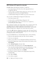
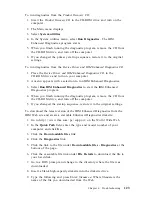
Page 140: ...nostics to diagnose and isolate hardware problems To start the IBM Enhanced Diagnostics program from the Product Recovery CD or the Device Driver and IBM Enhanced Diagnostics CD you might need to chan...

Page 141: ...en you finish running the diagnostic program remove the CD from the CD ROM drive and turn off the computer 5 If you changed the startup sequence restore it to the original settings To download the lat...

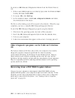
Page 142: ...ear on the screen For help press F1 Other diagnostic programs on the Software Selections CD The Software Selections CD that comes with your computer also contains diagnostic programs designed specific...

Page 143: ...owever no battery lasts forever If the battery fails the date time and configuration information including passwords are lost An error message is displayed when you turn on the computer See Lithium ba...

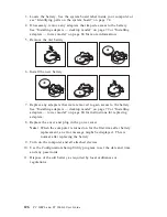
Page 144: ...ess to the battery See Installing adapters desktop model on page 79 or Installing adapters tower model on page 80 for instructions for replacing adapters 8 Replace the cover and plug in the power cord...

Page 145: ...Station Workstations U S http www ibm com pc us accessories Options by IBM U S http www ibm com pc us netfinity IBM Netfinity Servers U S You can select a country specific Web site from these pages He...

Page 146: ...btain warranty service Please have the following information ready when you call Machine Type and Model Serial numbers of your IBM hardware products Description of the problem Exact wording of any err...

Page 147: ...ing system or application program Getting customer support and service Purchasing an IBM PC hardware product entitles you to standard help and support during the warranty period If you need additional...

Page 148: ...n boards and online information services provide assistance through question and answer message areas live chat rooms searchable databases and more Technical information is available on a wide range o...

Page 149: ...y problems can be remotely diagnosed and corrected quickly and easily In addition to a modem a remote access application program is required This service is not available for servers There might be a...

Page 150: ...rmation for your system If possible be at your computer when you call In the U S and Canada these services are available 24 hours a day 7 days a week In the U K these services are available Monday thr...

Page 151: ...Zealand call 61 2 9354 4171 In all other countries contact your IBM reseller or IBM marketing representative Purchasing additional services During and after the warranty period you can purchase additi...

Page 152: ...age or as an annual contract with a 10 incident limit For more information about purchasing Enhanced PC Support see Ordering support line services on page 135 900 number operating system and hardware...

Page 153: ...ort In Canada contact IBM Direct at 1 800 465 7999 or 1 Call 1 800 465 3299 2 Select the HelpWare catalog In all other countries contact your IBM reseller or IBM marketing representative For more info...

Page 154: ...ents Availability of the services varies by product For more information about warranty upgrades and extensions In the U S call 1 800 426 4968 In Canada call 1 800 465 7999 In all other countries cont...

Page 155: ...Product Recovery CD or the Device Driver and IBM Enhanced Diagnostics CD They are not on the Software Selections CD You can use the CD to Install some software products directly from the CD on models...

Page 156: ...ructions on the screen or 1 In Access IBM click Customize For information about opening Access IBM see About Your Software 2 In the Customize menu click Install Software 3 When prompted insert the Sof...

Page 157: ...owing information The model and type M T numbers and the serial number S N for your computer are located on a label on the rear of the computer Device records Use the following tables to keep a record...

Page 158: ...l Connector A Serial Connector B USB Connector 1 USB Connector 2 Monitor Connector Audio Connectors Keyboard Connector 104 key keyboard Other Mouse Connector ScrollPoint mouse 2 button mouse Other 5 2...

Page 159: ...e from IBM or your reseller The term Machine means an IBM machine its features conversions upgrades elements or accessories or any combination of them The term Machine does not include any software pr...

Page 160: ...fication unsuitable physical or operating environment improper maintenance by you or failure caused by a product for which IBM is not responsible The warranty is voided by removal or alteration of Mac...

Page 161: ...art that replaces a removed part will assume the warranty service status of the removed part Before IBM or your reseller exchanges a Machine or part you agree to remove all features parts options alte...

Page 162: ...3 SPECIAL INCIDENTAL OR INDIRECT DAMAGES OR FOR ANY ECONOMIC CONSEQUENTIAL DAMAGES INCLUDING LOST PROFITS OR SAVINGS EVEN IF IBM ITS SUPPLIERS OR YOUR RESELLER IS INFORMED OF THEIR POSSIBILITY SOME J...

Page 163: ...will provide repair and exchange service for the Machine without charge under the type of service designated for the Machine and will manage and install engineering changes that apply to the Machine...

Page 164: ...ller replaces becomes its property and the replacement becomes yours You represent that all removed items are genuine and unaltered The replacement may not be new but will be in good working order and...

Page 165: ...egardless of the basis on which you are entitled to claim damages from IBM including fundamental breach negligence misrepresentation or other contract or tort claim IBM is liable for no more than 1 da...

Page 166: ...aragraph apply PEOPLE S REPUBLIC OF CHINA Governing Law The following is added to this Statement The laws of the State of New York govern this Statement INDIA Limitation of Liability The following rep...

Page 167: ...is provided in Albania Armenia Belarus Bosnia and Herzegovina Bulgaria Croatia Czech Republic Federal Republic of Yugoslavia Georgia Hungary Kazakhstan Kirghizia Former Yugoslav Republic of Macedonia...

Page 168: ...o of the first paragraph of this Section 1 death or personal injury or physical damage to your real property solely caused by IBM s negligence and 2 the amount of any other actual direct damages up to...

Page 169: ...em is added to this paragraph 3 breach of IBM s obligations implied by Section 12 of the Sale of Goods Act 1979 or Section 2 of the Supply of Goods and Services Act 1982 Applicability of suppliers and...

Page 170: ...of correctly processing providing and or receiving date data within and between the 20th and 21st centuries provided all other products for example software hardware and firmware used with the product...

Page 171: ...tates and or other countries Other company product and service names may be trademarks or service marks of others Alert on LAN HelpCenter HelpWare IBM IntelliStation LANClient Control Manager Netfinit...

Page 172: ...the equipment off and on the user is encouraged to try to correct the interference by one or more of the following measures Reorient or relocate the receiving antenna Increase the separation between t...

Page 173: ...installed and used in accordance with the instruction manual may cause harmful interference to radio communications Operation of this equipment in a residential area is likely to cause harmful interf...

Page 174: ...dification of the product including the fitting of non IBM option cards Federal Communications Commission FCC and telephone company requirements 1 This device complies with Part 68 of the FCC rules A...

Page 175: ...ed to present proof of purchase The telephone company may ask you to disconnect the device from the network until the problem has been corrected or until you are sure the device is not malfunctioning...

Page 176: ...nger Equivalence Number REN assigned to each terminal device provides an indication of the maximum number of terminals allowed to be connected to a telephone interface The termination on an interface...

Page 177: ...sont raccord s ensemble Cette pr caution est particuli rement importante dans les r gions rurales Avertissement L utilisateur ne doit pas tenter de faire ces raccordements lui m me il doit avoir recou...

Page 178: ...Type SVT or SJT three conductor cord a maximum of 15 feet in length and a parallel blade grounding type attachment plug rated 15 amperes 125 volts For units intended to be operated at 230 volts U S us...

Page 179: ...n Sudan Sweden Syria Togo Tunisia Turkey former USSR Vietnam former Yugoslavia Zaire Zimbabwe 13F9997 Denmark 14F0015 Bangladesh Burma Pakistan South Africa Sri Lanka 14F0033 Antigua Bahrain Brunei Ch...

Page 180: ...162 PC 300PL and PC 300GL User Guide...

Page 181: ...Setup Utility program 43 forgotten 46 setting 45 using 45 air circulation 11 America Online 131 antiglare filter 10 arranging workspace 9 asset id capability 32 assistance 127 audio features 34 ports...

Page 182: ...ting 39 updating 35 connecting cables external 96 input output devices 12 13 internal drives 84 connectors input output 12 13 on system board 70 74 cord power 11 cover lock 64 68 94 lock broken 115 pa...

Page 183: ...enhanced diagnostics 122 enhanced security 31 refid asf cover lock 31 erasing passwords 46 error messages resource conflicts 96 expansion slots 3 adapters 79 AGP 3 available 3 expansion slots continue...

Page 184: ...ed 42 locking 31 problems 116 speed changing 50 using 10 keyboard locking 31 keys 31 L LAN wake up requests 55 LANClient Control Manager LCCM 29 laser compliance statement xii lighting 10 lights indic...

Page 185: ...s available 62 installing 61 recording information 139 ordering support line services 135 P padlock loop 30 parallel port location 12 13 problems 119 passwords 42 administrator 45 computer startup 23...

Page 186: ...rce conflicts 79 82 96 resource conflicts error messages 96 ribbon cables 84 RPL description 28 S safety electrical ix screen filter 10 SCSI cables 85 installing devices 85 SDRAM 3 security 47 feature...

Page 187: ...SMA 29 T tape drive 82 84 technical support fee 133 technical support remote 131 technical support warranty 131 telephone assistance 131 telephone cable disconnecting 69 tower models 2 trademarks 153...

Page 188: ...warranty service 131 warranty statements 141 work area arranging 9 World Wide Web home page 127 129 write protecting diskettes 25 write protect switch setting 78 170 PC 300PL and PC 300GL User Guide...

Page 189: ......

Page 190: ...IBM Part Number 09N1180 Printed in U S A August 1999 9N118...

Reviews: