background image

Summary of Contents for 3277

Page 1: ... _ Maintenance Library Display Station Models 1 and 2 Troubleshooting Guide SY27 2314 5 ...

Page 2: ...d in Section 8 IDR M ID Reader Motorized Theory Maintenance Parts Catalog SY26 4188 To successfully use this manual and repair IBM 3277 display stations maintenance personnel should have a level of training equivalent to the 3270 system basic FE course Because the 3277 attaches to both local and remote control units an understanding of the control unit to which the display station is attached is a...

Page 3: ...14 5 3 5 1 Keyboard from Display Station 5 14 Section 3 Symptom Index 3 1 5 3 5 2 Keyboard Top Cover 5 14 3 1 Symptom Index Usage 3 1 5 3 5 3 Keyboard A mbly from Bottom Pan 5 14 3 2 Developing Symptoms 3 1 5 3 5 4 Audible Feedback Assembly 5 14 5 3 5 5 Keybutton 5 15 Section 4 Trouble hooting Diagrams 4 1 5 3 5 6 Type A Switch Module 5 15 5 3 5 7 Type A Spacebar Assemblies 5 17 Section 5 Checks A...

Page 4: ...Function With 3 9 Glow Only on CRT 3 8 Features Card Side View 6 15 3 10 Single Horizontal Line on CRT 3 8 6 14 Board Layout Pin Identification Data 3 11 Model 1 Raster 3 8 Pin Side View 6 16 3 12 Model 2 Raster 3 8 7 1 Model 1 Locations Front View 7 1 3 13 Cursor in Every Row 3 9 7 2 Model 1 Locations Left Side View 7 2 3 14 Box in Every Character Position 3 9 7 3 Model 1 Locations Rear View 7 3 ...

Page 5: ...l word PF program function POR power on reset DEL delete PS power supply DUP duplicate SLT solid logic technology EBCDIC extended binary coded decimal interchange code SMS standard modular system EC engineering change SOR start of record EOF end of field TB terminal board FE Field Engineering TCU transmission control unit Ferro ferro resonant transformer TEST REO test request FRU field replaceable...

Page 6: ... Pin is specified in the symbol Path to be followed after probing is determilled by probe result Car d Chanqe IndlCd rhat card or cards specified in symbol should be changed and new ones installed t Paqe Connector f dH dtes connection point between different sheets of the Troubleshooting Diagrams Uri aqe Connector Indicates connection between two parts of the same sheet or diagram Arrow leaving S ...

Page 7: ...res In some cases the Symptom Index points directly to a replaceable unit causing the problem Section 1 Maintenance Approach 1 1 3 2 Troubleshooting Diagrams The Customer Engineer is directed to Troubleshooting Diagrams from the Symptom Index The diagrams detail procedures to isolate a failing FRU or an out of tolerance adjustment The diagrams call out specific checks and observations that shouId ...

Page 8: ...try that matches the failure The Symptom Index tells what corrective action should be taken 1 2 4 Formatted Buffer Symptoms If an offline symptom does not become evident the entire display station including features must be tested with the buffer formatted The procedure described in paragraph 5 1 1 should be used with Test Pattern 1 to develop a symptom Stop the test as soon as a symptom becomes e...

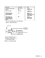
Page 9: ...e Diagram 2 1 A is a self contained device consisting of an anodized aluminum tube with a red and green indicator incorporated near the probe end A cable containing two wires and SLT type push on terminals leads from the sealed top end of the probe A plastic head with a threaded stud is at the probe end of the device Red and green indicators tell the state of the net being probed The three signal ...

Page 10: ...I11I1 I J U 0 t J N J 0 J Z en J U W Tip Z Q 8 0 0 B IBM General Logic Probe Diagram 2 1 Logic Probes 2 2 I 1II1 I I I IIII I Q w Z 0 z w Z 0 0 Z 0 J Cable Connect to any 003 pin Push Qn Connectors J w III 0 II Q u e 0 J J ct II w Z W e Z xl Cable ...

Page 11: ...k of the card A start of record SOR character precedes the message and an end of card character and a check character follow the message The SOR character initiates the read operation but is not transferred to the display station The card is used to check the performanct of the operator identification card reader Two test cards are shipped with each card reader 2 2 DIAGNOSTIC PROGRAMS Diagnostic p...

Page 12: ...the screen 22 1 4 Test Pattern 5 Diagram 2 7 Test Pattern 5 loads the display station buffer with all available uppercase and lowercase character codes The 2 4 audible alarm if installed sounds when this pattern appears on the screen 2 2 2 Requesting RFT Patterns RFT patterns can be requested for 3277 Display Stations attached to a local control unit 3272 or to a remote control unit 3271 Patterns ...

Page 13: ...L PEN TEST SEL PEN TEST ADR 6G48 Model 1 Patternl Model 2 Pattern Notes 1 AOR ctppears only when patter Ie called Irr n L fEP 2 NON OISPLA Y Ie not displayed 3 Use Olawam 2 8 to determlnP unique chilrilctp r rr p I elr nts wiWIl A CII vr lllTe 1 1 ludges lrE u ed Diagram 2 4 Test Pattern 1 USA EBCDIC ToOls and Diagnostic Programs 2 5 ...

Page 14: ...FOR 3275 1 3277 1 H H ALIGNMENT H H UNPROTECTED AREA H H 0 ADR 6040 H EEEEEEEEEEEEEEEEEEEEEEEEEEEEEEEEEEEEEEEE Note AOR appears only when pattern IS called In from OL TEP Diagram 2 5 Test Pattern 2 Not AOR dpf H ars HliV when pattern IS c Jlled 111 from OL TEP Diagram 2 6 Test Pattern 3 2 6 ...

Page 15: ...3456789 ABCDEFGHIJKLMNOPQRSTUVWXYZ8123456789 1 n0 1 j t Qt I J L CHECK55555 EOfVl CHECK99 Model 1 Pattern Note I Jse DlagrnJn 28 to deterrninf unique Lhdrdcter repldU n1t nts twn A I l T 1 fHjlJd WS drt lJSPU Diagram 27 fest Pattern 5 USA EBCDIC Tools dnd Diagnostic Programs 2 7 ...

Page 16: ...ters in the hexadecimal number must be entered in uppercase 3 Press TEST REQ key INPUT INHIBITED indicator should come on 4 The desired pattern should appear within 15 seconds If INPUT INHIBITED indicator stays on and the pattern does not appear proceed as follows 2 8 a Repeat the request while ensuring that steps 1 3 are performed correctly b Check that the operating system and the BTAM applicati...

Page 17: ...t is shipped with each control unit Control unit MLTGs also contain this information Most OLT routines apply to control units The following three routines apply to display stations 1 KEY This routine handles manually generated inter rupts from the keyboard selector light pen and program function keyboard The results of the interrupts are presented on the display station screen informing the CE of ...

Page 18: ...ht column may also specify an adjustment procedure in Section 5 Diagrams 3 1 through 3 24 show both correct and some incorrect display images The symptom Iist refers to these illustrations to aid in identifying display station symptoms As an aid to rapid repair diagrams that show incorrect display images also specify the repair action Section 3 SYmptom Index 3 2 DEVELOPING SYMPTOMS Display station...

Page 19: ... focus Diag 3 18 6 Dual intensity problems or characters displayed that should not 7 Display erratic e g display flashes characters move more than one cursor 8 Screen full of lines 9 Retrace unblanked 10 Random data on screen INPUT INHIBITED lighted 11 Cursor on left side in all rows 12 One dot at character location zero cursor position C Display Position and Size 1 Horizontal size too large or to...

Page 20: ...rs displayed E Cursor 1 No cursor on screen but rest of display normal no Device Check 2 No cursor with INPUT INHIBITED lighted Cursor cannot be returned to screen by Power On Reset or CLEAR key 3 Cursor appears normally INPUT INHIBITED lighted 4 Cursor under all or most character positions and Device Check indicated INPUT INHIBITED lighted Diag 3 13 5 Cursor under all character positions but Devi...

Page 21: ...3 Diagonal row of dots appears starting at lower left corner of screen as characters enter INPUT INHIBITED not lighted Change card J2 B Character Keys 1 Wrong character for one key 2 Wrong character for more than one key 3 No characters enter for all keys 3a Correct character enters but INPUT INHIBITED lights for one or more keys 4 No character enters for all keys cursor advances with each key dep...

Page 22: ...t should not 3 SELECTOR LIGHT PEN MALFUNCTIONS A Nothing happens when tip switch closed B Lines appear and remain through all detectable characters with detect attempted C Lines always appear through all detectable characters even when pen not used 0 Data not entered when selector light pen initiates entry into system 1 INPUT INHIBITED does not light 2 INPUT INHIBITED lights E Selector light pen a...

Page 23: ...am Sheet or Direct Action Repair Sheet 23 Sheet 26 Sheet 26 Sheet 26 Change cards G2 H2 J2 Sheet 9 Sheet 10 Sheet 7 Sheet 27 1 Selector pen changes designator character correctly but INPUT INHIBITED lights Change card 02 2 Selector pen fails to set MDT and INPUT INHIBITED does not light Change card M2 3 Keyboard fails to set MDT Change cards A2 C2 G Programmed audible alarm failure Sheet 21 H Keyb...

Page 24: ...1 malfunction produces similar results Adjust yoke 5 2 1 4 Diagram 3 5 Yoke Back Too Far on CRT Neck See Diagram 2 4 for greater detail of the test pattern data Diagram 3 2 Test Pattern 1 Model 2 See Diagram 2 6 for greater detail of the test pattern data Diagram 3 4 Test Pattern 3 Model 1 malfunction produces similar results Adjust yoke 5 2 1 4 Diagram 3 6 Yoke Tilted Symptom Index 3 7 ...

Page 25: ...gram 3 9 Glow Only on CRT Troubleshoot on Diag 4 1 Sh 5 182 Diagram 3 11 Model 1 Raster 3 8 Model 1 malfunction produces similar results Adjust analog card Model 1 5 2 1 6 Mod 1 2 5 2 1 7 Diagram 3 8 Character Height Too Small Troubleshoot on Diag4 1 Sh 4 181 Diagram 3 10 Single Horizontal line on CRT Troubleshoot on Diag 4 1 Sh 5 182 Diagram 3 12 Model 2 Raster ...

Page 26: ... 6102 Diagram 3 15 No Horizontal Sync Model 1 display is same except for size Diagram 3 17 Correct Display after POR Model 1 malfunction produces similar results Change card J2 if INPUT INHIBITED is on Change card K2 if off Diagram 3 14 Box in Every Character Position This failure applies to Model 2 displays only Troubleshoot on Diag 4 1 Sh 7 1C3 Diagram 3 16 No Interrow Spacing Model 2 malfunctio...

Page 27: ...n produces similar results The pattern displayed is data dependent Diagram 3 23 Vertical Yoke Open t 3 10 Model 1 malfunction produces similar results Diagram 3 20 Open in Yoke Horizontal Winding t Model 1 malfunction produces similar results The vertical bar appears in every row that has data Diagram 3 22 Horizontal Yoke Open t t Connector P1 loose on analog card can cause similar symptom Check P...

Page 28: ...ed result use the part of the flowchart labeled Other The seven logic probe observations specified in the flowcharts and their definitions are as follows 1 Red solid red 2 Green solid green 3 Red Blink solid green with one and only one red blink Section 4 Troubleshooting Diagrams 4 Green Blink solid red with one and only one green blink 5 Pulsing Red solid green with regular red pulses Any frequen...

Page 29: ...e installed and seated properly Diagram 6 12 shows logic board card plugging for display stations with no 4 2 features 1 2 board Diagram 6 13 shows card plugging for display stations that have features installed 2 3 board The logic probe is used extensively in this section to isolate failing cards Ensure that the logic probe is operating correctly before troubleshooting Use the procedure in paragr...

Page 30: ...ay Station Troubleshooting Diagrams Sheet 1 of 29 Trouble is probably in display stotion If further verlfic otlon is required to pnlYe trouble is in display stotion perform operotions described at left Assume that trouble is in displ ay station Use Symptom Index and Troubleshooting Diagrams to resolve problem Originol failur was probably a loose cooxial ccable connection Or on intermittent problem...

Page 31: ...nterelockwise Press and hold INTEN CRT switch Turn Brightness control toward maximum Sheet 4 Diagram 4 1 Display Station Troubleshooting Diagrams Sheet 2 of 29 No Compare display with Diags 3 19 to 3 23 Release INTEN CRT switch Turn pawer off Replace feature card s A2 82 M2 N2 Chonge analog card Mod 1 5 3 3 3 Mod 2 5 3 3 4 Power on and adjust 5 2 n Yes Sheet 4 Yes Yes Turn power off Replace featur...

Page 32: ...sure resistance between CRT pins I ond 4 Chonge ferro transforMer Mod I 5 3 2 6 5 3 2 7 Mod 2 5 3 2 8 5 3 2 9 Diagram 4 1 Display Station Troubleshooting Diagrams Sheet 3 of 29 Sheet e Turn power off e Remove CRT sock t ond cone shield 5 3 3 2 e Connect CRT socket e Tum power aH e Remove CRT socket e Measure r istance between CRT piN I ond 14 Check cobl ond CRT ocket for l _ or broken connections ...

Page 33: ...4 of 29 Meaoure following voltage at HVPS 011 PS2 10 de return Oiag 7 14 Meaoure following voltages with YOM on 15Y scale Reference negotive leod to de return Measure voltage on voltage distribution board terminol 11 Oiog 7 11 distribution boord Verify repoir Remove push on connec tar Ifroln supply pin 3 IN and 1 ___ voltage at connector on wi Change analog ecwd Mod I 5 3 3 3 Mod 2 5 3 3 4 Power o...

Page 34: ...Oltage distribution boord Dioq 7 61 Verily repair Turn power off Change analog cord Moo I 5 3 3 3 Mod 2 5 3 3 4 Power On ono odivst 5 2 1 Diagram 4 1 Display Station Troublnhooting Diagrams Sheet 5 of 29 CheCk vo oge Q C k2B ile tur in9 B ight lE t5 control f o 0 1 to Turn power off Change con rol 5 3 3 61 Verd y repair Remove left cover Adjvst Focus using rocus Contro 0 H V JX wer ILlpp 5 2 3 Yes...

Page 35: ...pen right side cover Remove feature cordIs A2 82 M2 N21 r n power off Change analog card Mod 1 5 3 3 3 Mod 2 5 3 3 4 I Power on and adjust 5 2 I Diagram 4 1 Display Station Troubleshooting Diagrams Sheet 6 of 29 Turn power off Remove right side cover Remove feature card s A2 82 M2 N2 Turn power on Sheet 8 ...

Page 36: ...ble from control unit Turn power on Tum power off Repair security keylock or change switch 5 3 7 Diagram 4 1 Displav Station Troubleshooting Diagrams Sheet 7 of 29 Remove right side cover Remove front cover Disconnect control unit cable Green Perform Test Pattern 1 procedure 5 1 1 Check for parity check after each key Sheet 17 No Yes Troublelhooting Diagrams 4 9 ...

Page 37: ...ho Zl to Z4 Move keyboard cable from Z4 Ia Zl Replace keyboard feature cards A2 82 Tum power on Test keyboard operations Turn power off Replace light pen feature card 1M2 Turn power on Test keyboard operations Turn power off Replace cord reader feature cord IN2l Move keyboard coble frolT Zl to Z4 Yes No Diagram 4 1 Display Station Troubleshooting Diagrams Sheet 8 of 29 4 10 Replace keyboard featur...

Page 38: ... Remove feature card s IA2 82 M2 N21 Turn power on I Probe while turning I power on Sheet 8 Probe while turning power on Probe while turning power on Diagram 4 1 Display Station Troubleshooting Diagrams Sheet 9 of 29 Sheet 10 Troubleshooting Diagrams 4 11 ...

Page 39: ...er on Otfter Other Other Green Other Model 2 Only Yes Other Other Other Diagram 4 1 Display Station Troubleshooting Di gr ms Sheet 10 of 29 4 12 Turn power off Open front cover Disconnect CU cable Remove feature cord s A2 82 M2 N2 Green Other Turn power off Remove feature cord s A2 82 M2 N2 Turn power on ...

Page 40: ...abl from control lJnil Tu n po_ on Diagram 4 1 Displav Station Troubleshooting Diagrams Sheet 11 of 291 Display station mUlt be attached 10 an active Turn po_r off Repair cabl Or change security k ylock switch 5 J 7 V rl fi Troubleshooting Diagrams 4 13 ...

Page 41: ...e bar Probe 1 B2505 G G B2S08 R Probe pins Probe pin B2509 G listed in B2502 G B2U05 G Probe while alternately B2Ml0 G B2U09 G pressing a character key B2Mll G R and RESET key B2513 G G PrObe pi No P ohif pin Yes I Diagram 4 1_ Display Station Troubleshooting Diagrar ns Sheet 12 of 291 4 14 ...

Page 42: ... CLEAR key Customer program error All fields defined as protected Probe whil pr sing a character key Diagram 4 1 Display Station Troubleshooting Diagrams Sheet 13 of 29 Red and Green Other Sheet 21 Troubltllhooti 0 4 15 ...

Page 43: ...while pressin8 a choroc r key Probe while holdirIQ key pressed _ _ _ _ _ L _ _ _ _ _ J Pulsing Green Shee 21 2Cl D m 4 1 Display Stlltion Troubleshooting Dill8raml Sheet 14 of 29 4 18 Shee 18 K Shee 21 Ves Shee 9 No ...

Page 44: ...up OM row e Pr_ leey briefly M Sheet 16 No No No No SM Mod I Olag 3 1 Mod 2 Olag 3 2 Met 21 Probe while holding key ed Diagram 4 1 Display Station Troubleshooting Diagrams Sheet 15 of 29 Y Probe while holding leey d Sheet 21 f Probe while holdl keyp Other G n Other Troubleshooting Diagrams 4 17 ...

Page 45: ...Diagram 4 1 Display Station Troubleshooting Diagrams Sheet 16 of 29 4 18 Either trouble disappeored or buffer wos fully protected when trouble reported Probe while holding key pre sed Probe while holding _ key prnsed Red ond Gr n ...

Page 46: ...Sheet 16 Sheet 7 No No Otner _ 1 r Probe while holding _ I key pressed Yes Sheet 21 Diagram 4 1 Display Station Troubleshooting Diagrams Sheet 17 of 29 Troubleshooting Diagrams 4 19 ...

Page 47: ...le holdir 9 ERA Sf EOF key pressed Probe while holdir 9 ERASE EOF key pressed Diagram 4 1 Display Station Troubleshooting Diagrams Sheet 18 of 29 4 20 Probe while olding ERASE INPUT key pressed Sheet 11 heet 14 ...

Page 48: ...Sheet 16 Pulsing Green She t 21 Probe while holding _ key pressed Diagram 4 1 Display Station Troubleshooting Diagrams Sheet 19 of 291 Probe while pressing RESET key Troubleshooting Diagrams 4 21 ...

Page 49: ...le pressing foiling key Diagram 4 1 Display Station Troubleshooting Diagrams Sheet 20 of 29 4 22 R d 81 llk IEcK h Imp dlph vme Ie kfl Y pr st d dno character Sheel9 Chonge audible feedback assembly No if foilure still occurs Replace original cord Change defective keybutton 5 3 5 5 ...

Page 50: ...ard ossembly 5 3 5 3 e Type 8 Chonge circuit board 5 3 5 11 Diagram 4 1 Display Station Troubleshooting Diagrams Sheet 21 of 29 I r o s d I 15 3 5 I I Remove top cover I 5 3 5 2 I rd I battom pon 5 3 5 3 Other Probe while ent ng character in ned to lost position Troubleshooting Diagqms 23 ...

Page 51: ...Other Probe while holding tip switch closed e Chonge selector light pen 5 3 81 e Verify fix Diagram 4 1 Display Station Trouble hooting Diagrams Sheet 22 of 291 4 24 ...

Page 52: ...wing order 1 PC board 5 3 2 1 2 AC capacitor 5 3 2 3 3 Ferro transformer Mod 1 5 3 2 6 5 3 2 7 Mod 2 5 3 2 8 5 3 2 9 Check for repair ofter each unit installed Ch ck prime power bOl and connectors Change line cord Change prime powerbox Mod 1 5 3 2 4 Mod 2 5 3 2 5 if no shorts or evident Change fuse Fl Reconn ct all conn ctors Diagram 4 1 DispilY Stltion Troubleshooting Dillll llmi Sheet 23 of 29 V...

Page 53: ... 2 5 3 2 8 5 3 2 __ 1 Change ferro transformer Mod I 5 3 2 6 5 3 2 7 Mod 2 5 3 2 8 5 3 2 9 V s Diagram 4 1 Display Station Troubleshooting Diagrams Sheet 24 of 29 4 26 No No Change fuse Disconnect analog power plug Turn power on Measure 8V Ves Chonge PC board 5 3 2 11 Ves Change onalog card Mod 1 5 3 3 3 Mod 2 5 3 3 4 Power on and adjust 5 2 11 ...

Page 54: ...en off Use wiring diagram YAO11 to locate short in wiring 10 logic gote or ilOlate 10 logic card s by removing all cards from gate If nat in wiring or cards change logic board Yes Change PC board 5 3 2 1 Replace plug P3 on analog cord e Remove push an connector to pin 5 of HV power IUpply V e Tum pawer on for about 1 minute then off Change analog card Mod 1 5 3 3 3 Mad 2 5 3 3 4 R place push an co...

Page 55: ...y all offline functIons are correct Swap coaxIal sIgnal cobl wIth known good devic Yes Check cooxial coble from input connector to board Yes Diagram 4 1 Display Station Troubleshooting Diagrams Sheet 26 of 29 ...

Page 56: ...ug for approx imote Iy 400 ohms Check display station power cabling from card reader ex nnector to ferro transformer No Measure reoder motor resistance between pins 10 and 24 of reoder cable plug for approximately 400 ohms Yes Refe to IDR M 10 Reode MOtorized Theory Maintenance Par Catalog Diagram 4 1 Display Station Troubleshooting Diagrams Sheet 27 of 29 e Press RESET CLEAR and RESET keys Feed t...

Page 57: ...f 0IA 2D07 and B03 heck coble ground 01 01A N2DOB Ye Connect signal and grl vr ld wires orredly Te t cad reade operations Returr to cudomer I I Diagram 4 1 Display Station Troubleshooting Diagrams Sheet 28 of 29 4 30 Disconnect reader cable from OIA N2007 8 3 and 008 Set VOM on 5V de Connect minus 1 l ac1 on wire formerly attached to N2008 Check Ihe two signal wires for approximateI v V ac as lest...

Page 58: ...t s 1000IcPIfIOVAOII for WIr routine CII In 10110 otdo I LVPC Boord 5 3 2 11 2 Ferro transformer 5 3 2 615 3 291 o ck for repeir after chstep Chock In fol1owl o do 1 01A A1M2cord 2 34 V WIring from tu 10 boord s 1000Ie pogo YAOII fo wire routine 3 34 0 ont v on bGo d It 0IA A1K8B04 With ohmme stili connected remove co dsiftOIA A1 nd the keybo rd connector In OIA Al 21124 one tln e until Short IS I...

Page 59: ...uld be formed properly with correct inter row spacing 6 Vary Brightness control Set it where high intensity characters have proper brightness Section 5 Checks Adjustments and Removals 7 Vary Contrast control Set it where normal intensity characters contrast with high intensity characters at desired level 5 1 1 2 Security Keylock Test Optional Feature 1 Turn security key off vertical position All d...

Page 60: ...ttached If a pen is not attached press CLEAR key All characters remaining 5 2 on screen should disappear and cursor shou d reappear in first character position in first row Press RESET key 28 Proceed to paragraph 5 1 1 5 if display station has an operator identification card reader attached If a card reader is not attached test is completed Turn power off and reconnect control unit signal cable 5 ...

Page 61: ...ear on screen and INPUT INHIBITED should go out 23 Press CLEAR key then RESET key All characters should disappear from screen and cursor should reappear in character location O 24 Press Backspace key two times 25 Press any character key Audible alarm feature should sound when key is pressed if feature is installed 26 If an operator identification card reader is attached proceed to step 27 Turn pow...

Page 62: ...y appear as a defec tive HV power supply or analog card If excessive trouble is experienced with either of the two assemblies check the 5 4 arc suppression circuitry as listed below Arc suppression circuitry is located on the arc suppression board Zl Diagram 7 15 on Model 1 display stations and on the voltage distribution board TB1 Diagram 7 11 on Model 2 display stations Visual Checks 1 Check for...

Page 63: ...tch modules spacebar assembly support modules Type A only circuit board and elec tronics assemblv Type B only and the audible response device Do not attempt to repair any other keyboard units While performing the following checks the keyboard assembly should be visually inspected for shorts or grounds that could cause erratic operation or erroneous results A faulty keyboard assembly should be repl...

Page 64: ...guration observed in step 2 with configuration for desired character shown in Diagram 6 5 or 6 6 5 1 4 4 Shift Key Modules Type A Keyboards Only Two SHIFT keys and the shift LOCK key NUMERIC and NUM LOCK keys on data entry keyboards generate an input signal to the keyboard assembly encoder The encoder generates upshift character codes of the characters appearing on the top half of the keyboard key...

Page 65: ... INDIC neon This jumper disables vertical deflection and produces a single horizontal trace across approximate middle of screen 3 Loosen yoke clamp and rotate yoke until horizontal trace is parallel to or coincides with horizontal lines on alignment mask 4 Ensure that yoke is firmly seated against CRT bell while maintaining horizontal alignment obtained in step 3 5 Tighten yoke clamp loosened in s...

Page 66: ...t bottom trace of characters in last row coincides with center of line C on alignment mask When adjusted correctly overall height of display image should be 3 3 inches from line A to line C 5 8 3 Remove vertical skip disabling jumper Display image should appear nearly normal with inter row spacing Overall image may be too large or too small Model 2 Inter Row Spacing Adjust Row Spacing poten tiomet...

Page 67: ... removing and replacing a unit in the Modell display station differs from the procedure used with the Model 2 display station a separate paragraph describing the unique procedure is presented All removal and replacement Actuator Power Switch Plungers 2 procedures require that the desired unit has been made accessible by the removal of necessary cOIIers and made safe by the removal of power The top...

Page 68: ...er and pull 12V regulator card from socket in same manner as an SMS card is removed from a card socket 2 Replace card by lifting plastic retainer and sliding card into the SMS socket 3 Perform 12V regulator card adjustment paragraph 5 2 2 5 10 5 3 2 3 AC Capacitor 1 Remove rubber boot from top of capacitor and slide back on wire leads 2 Holding insulated handle of a screwdriver short out capacitor...

Page 69: ...f chassis 5 Release the two clamps at side of chassis holding upper chassis to base chassis 6 Release spring catches on rear guides and slide upper chassis slightly to front to disengage the two rear guides 7 Lift upper chassis off base chassis and place upper chassis on a flat surface 8 Remove ac capacitor per paragraph 5 3 2 3 9 If a card reader is attached remove access cover on ferro cover ove...

Page 70: ...der ensuring that CRT grounding spring step 10 and yoke shield ground wire s step 8 are reconnected 20 Perform all Model 1 display image adjustments 5 2 1 through 5 2 1 6 5 12 Model 2 1 Disconnect power cord at display station under front cover 2 Remove left right and top covers 5 3 1 2 3 Remove Contrast and Brightness control knobs 4 Mark position of power control actuator assembly on left side r...

Page 71: ...nnectors at top of analog card 2 Loosen the two captive screws passing through analog card and into wire form These two screws have large knurled heads and a spacer on them 3 UnpJug bottom connector 4 Remove analog card from machine 5 Remove the two screws and spacers from old analog card 6 Reassemble screws and spacers in new analog card 7 Plug in bottom connector 8 Replace analog card in machine...

Page 72: ... paragraphs 5 3 5 6 through 5 3 5 8 apply only to Type A and paragraphs 5 3 5 9 through 5 3 5 11 apply only to Type B Ensure that the correct procedure is used The following equipment may be required 5 14 Keytop puller tool Isopropyl alcohol Cloth lint free PN 9900373 preferred PN 75475 or PN 627953 PN 2200200 or IBM tape transport cleaner PN 453511 PN 2108930 or tissue PN 2123106 5 3 5 1 Keyboard...

Page 73: ...e two small flat pointed tools from box containing new module and slip one down the inside face of each D bracket retainer to force brackets away from locking channels on plastic case of old module Diagram 5 2 3 With flat tools in this position grip shouldered portion of switch module plunger with pliers and pull switch module straight out CAUTION In the next step do not apply the soldering iron f...

Page 74: ...ring POSitioning Type A 5 16 2 Insert module into keyboard switch mounting frame with orientation arrow on top of module pointed in the same direction as arrows on other modules Diagram 5 6 As module is inserted be sure plunger return spring seats on raised boss on bottom of mounting frame and that the four terminals extend through holes in printed circuit board Diagram 5 6 Switch Module Orientati...

Page 75: ...ock guide modules firmly in place 3 Insert spacebar guides in spacebar guide modules and drop spacebar in place 4 Holding torsion bar at a suitable angle and position insert end of torsion bar in the hole in one spacebar guide Diagram 5 8 At the same time engage torsion bar with retaining lugs on guide module Lower torsion bar to horizontal Flex it as during removal and insert other end simultaneo...

Page 76: ... 3 5 10 for spacebar removal if spacebar module is to be replaced 1 Ensure that all small particles that might contam inate the keyboard assembly are removed from the work area 2 Record locations of keybuttons in area of module that is being replaced Remove keybutton from faulty module and from as many others as may be required to provide enough work space 3 Place keyboard assembly upside down in ...

Page 77: ... 5 12 and key module flyplates by carefully wiping each with a lint free cloth dampened with isopropyl alcohol 8e careful not to dislodge or remove flyplates from key modules 4 Align the holding screw holes through base plate PC board insulator and top insulator if present Diagram 7 18 shows the correct locations of these components Lower the all keys assembly into place 5 Carefully slide one corn...

Page 78: ... paragraph 5 3 5 9B 5 3 6 Audible Alarm Optional Feature The audible alarm device circuitry is packaged in a small metal box mounted on the base chassis beneath the CRT inside the front cover The audible alarm box is mounted vertically on Model 1 display stations and horizontally on Model 2 display stations 1 Remove front cover 2 Remove audible alarm box from chassis Box can be removed from snap f...

Page 79: ...ctions for repairing keyboard faults This section provides miscellaneous main tenance aids to supplement the existing procedures These aids are not intended to replace the existing procedures CEMs or other published data 5A 1 Ceaning The importance of cleanliness when servicing Type B keyboards cannot be overemphasized Any particle between the key module flyplate and the printed circuit board is a...

Page 80: ... the base plate and the ground pin 008 at the interface signal connector KB 1 5 4 7 Ground Loop Isolation Nonconductive inserts have been added to the base plate holding screws on some keyboard assemblies to isolate the base plate and PC board dc ground from the all keys assembly With the keyboard assembly disconnected from the 3277 check to ensure that the base plate and all keys assembly are not...

Page 81: ...rence Data toward the operator turns display station power on The overall displayed image is made brighter by rotating the Brightness control outer knob clockwise the image is made dimmer by rotating the knob counterclockwise The Contrast control inner knob is on a concentric shaft with the Brightness control Rotating the Contrast control clockwise reduces the difference in contrast between high a...

Page 82: ...otentiometer located on the analog card Turning the control varies 6 2 spacing between character rows and thus determines the overall height of the displayed image The ROW SPACING control is not used in Model 1 display stations 6 1 2 6 TOP MARGIN This control is a screwdriver adjustable potentiometer located on the analog card The control sets the top reference line on the CRT from which all other...

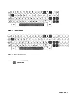
Page 83: ...lay station circuitry from possible damage 6 3 KEYBOARDS Optional Feature Four keyboards are used with 321 1 Display Stations Keyboards of the same type are interchangeable among display stations having keyboard adapter circuitry installed EBCDIC is the basic code used on all keyboards 6 3 1 1 Typewriter Keyboard The typewriter keyboard uses a standard typewriter key layout of 66 keys An additiona...

Page 84: ...including the symbols I logical or and logical not Option B provides the 64 ASCII character set but substitutes exclamation point for logical or and 1 circumflex for logical not 6 5 REFERENCE DIAGRAMS Diagrams 6 7 through 6 14 contain reference data that can be helpful in maintaining IBM 3277 Display Stations Display station data flow is shown in Diagram FO l a foldout page located at the back of ...

Page 85: ...Diagram 6 2 Typewriter Keyboard 8 CDCDCDCDwCDCDGJGJm CD 880GO 0000080GJG0wB 8 GOG B000000008GJGJ GGG G000000GCJCJwG 8GB un J Diagram 6 3 Operator Console Keyboard Typamatic Keys Reference Data 6 5 ...

Page 86: ...EL Q nl T mA0 mmm Gt l WWWWUUl UWWUJ Pf4 U r lnm f mmmmm L JWWWWWl UV JWLJ L J Data Entry Keyboard 8 c JGJGJCDCD GOmGGG GG r 0m neD f mmmmGr l r lG lQj E L U T l Jl UWWW PF4 DEL Q f l nmAmmmm G WWWWUUl UWWUJ PF5 r l mn mmmmmo L JwWW W W l UV VWLJ L J BET J ENTER Typamatic Keys o Numeric Keys Diagram 6 4 Data Entry Keyboards ...

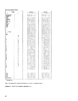
Page 87: ... 1 0 0 001 100 1 1 1 001 101 000 001 1 0 1 0 1 1 001 1 0 1 1 0 1 001 101 1 1 0 001 1 100 0 0 001110011 001 1 101 0 1 001110110 001111001 Lower Shift o 1 234 5 6 7 P 000101111 000 1 0 1 100 00101 1 000 00101 101 1 000100011 000100000 001 100 0 0 1 001011101 001 1 1 101 0 o 1 0 0 0 0 0 00 000 1 0 1 0 1 0 000110001 000 1 100 1 0 000110100 000 1 101 1 1 000 1 001 10 000 1 0 1 001 111 1 000 1 0 111 100...

Page 88: ... 1 1 1 1 0 1 1 1 0 1 1 1 1 1 0 0 0 0 1 1 1 1 1 0 0 1 1 o 1 0 0 1 0 1 1 1 011000001 001 100 0 1 0 001100100 o 0 1 1 0 0 1 1 1 001101000 o 0 1 1 0 1 0 1 1 1 0 0 1 1 1 1 0 0 Lower Shift o 1 234 5 6 7 P 000 1 0 1 1 1 1 000 1 0 1 100 00101 1 000 o 0 1 0 1 1 0 1 1 000 1 000 1 1 000 1 0 0 0 0 0 001100001 o 0 1 0 1 1 1 0 1 o 0 1 1 1 1 0 1 0 o 1 000 0 0 0 0 000 1 001 10 1 0 0 1 1 1 0 0 1 000 1 0 1 0 1 0 00...

Page 89: ...Austrian Belgian Danish Finnish United Keyboard Language EBCDIC ASCII A ASCII B German French Norwegian Swedish Italian Portuguese SPJOISh Kingdom Code 01234561P Key U Shift a Shift l Shift Shift Pts f 0101 101 10 Graphic U a l s Pt Key j Shift r A Shift A Shift 0 Shift N Shift 0111 101 1 1 Graphic A k A 0 N Key o Shift o Shift o Shift A Sh tt to lll 01 1 1 1 1 U j Graphic f u 0 0 0 n A u ftl Key ...

Page 90: ... 9 Fets Out Bits 0 9 480 Storage and Gate 480 character Serial Shift Gt message buffer Shift Fets and gates 02 Model 2 9065 MB011 061 Model 2 Contains TQ Ser in Bits 0 9 960 Storage and Gate 960 character message buffer and gates E2 L514 KA111 121 Contains line driver Data to Control Unit Data to Control Unit SE RDES and Special and line receiver Data to Driver Data from Driver Receiver Circuits I...

Page 91: ...Step Row Ctr display indicators Horiz Sync Blank CRT at Video Output Row 0 Row 1 Last R0IIIt End Screen Unblank Shift Fets I Vertical Retrace Bump Display Serial Shift GT K2 9058 MC011 091 Contains gates to Fets Out Bits 2 9 Pre ROS Bits 2 3 and Line Buffer and M1 line buffer ROS Shift Line Buff 7 Bits 4 5 6 and 8 Character Generator 9070 register line Blank CRT at Video from Line Buffer Non M2 bu...

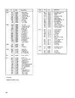
Page 92: ...creen S05 KM031 Keybd Bit 0 P04 KF181 Up Line S08 KM031 Keybd Bit 1 502 KF151 Last Row 509 KM031 Keybd Bit 2 505 KF141 Blank CRT at Video 513 KM021 Keybd Parity Bit Output U05 KM031 Keybd Bit 4 509 KF141 Force Unblank Line U09 KM031 Keybd Bit 6 512 KF171 Bump Display U13 KM011 Insert Csr Bit 9 S13 KF171 Vertical Retrace U02 KF141 Dev Check A C2 P04 MG051 POR Ul0 KF141 Horiz Sync 502 MG051 POR 503 ...

Page 93: ...m 6 10 Keybc8d Future Jump o Shift Jumper Add wire A2B06 to A2008 Remowwire A2B06 to A2008 Add wire B4B12 to B4oo8 Remove wire if installed B5B03 to B5008 Add wires B4B12 to 84008 B5B03 to B5008 To Connector KB 2 May not be present on all keyboards Key Modules Encoder 7 ___J P S tr obe p in R II To Connector KB 1 MOS Each key module except RESET and the shift keys generates two active inputs to th...

Page 94: ...Line Buffer and Char Gen K2 I 5wedish F innish Line Buffer and Char Gen K2 I Norwegian Danish Line Buffer and Char Ger K2 I Spanish Line Buffer and Char Gen K2 I Portuguese Line Buffer and Char Gen K2 2 US English EBCDIC Li ne Buffer and Char G en K2 2 US Er glish ASCII A Line Buffer and Char Gen K2 2 US English ASCII B Line Buffer and Char Gen K2 2 UK English line Buffer and Char Gen K2 2 German ...

Page 95: ...en K2 1 US English ASCII A Line Buffer and Char Gen K2 1 US English ASCII B Line Buffer and Char Gen K2 1 UK English line Buffer and Char Gen K2 1 German line Buffer and Char Gen K2 1 Swedish l innish Line Buffer and Char Gen K2 1 Norwegian Danish line Buffer and Char Gen l 2 I Spanish Line Buffer and Char Gen K2 I Portuguese Line Buffer and Char Gen K2 2 US English EBCDIC Line Buffer and Char Gen...

Page 96: ... o 0 0 0 0 0 0 0 0 0 0 0 0 o oo oeo 0 0 0 0 o oeoo o 0 o o o o 0 o 0 0 o 0 0 13 14 I 2 6 3 0000 4 5 Notes o 0 0 0 0 Z40 0 0 0 0 0 o 0 0 0 0 0 0 0 0 0 0 0 0 0 0 0 Return 5V Bus W21 Bus Wl1 Model 2 only I 5V IS found on all 003 J03 POJ InC U03 pins 2 DC return ground is found on III 008 JOB P08 InC U08 pins 3 8VisfoundonpinE2011 4 12V is found on pins 02006 F2006 E4006 M2D06 and K2D06 5 J 4Visfoundo...

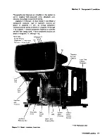
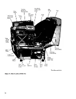
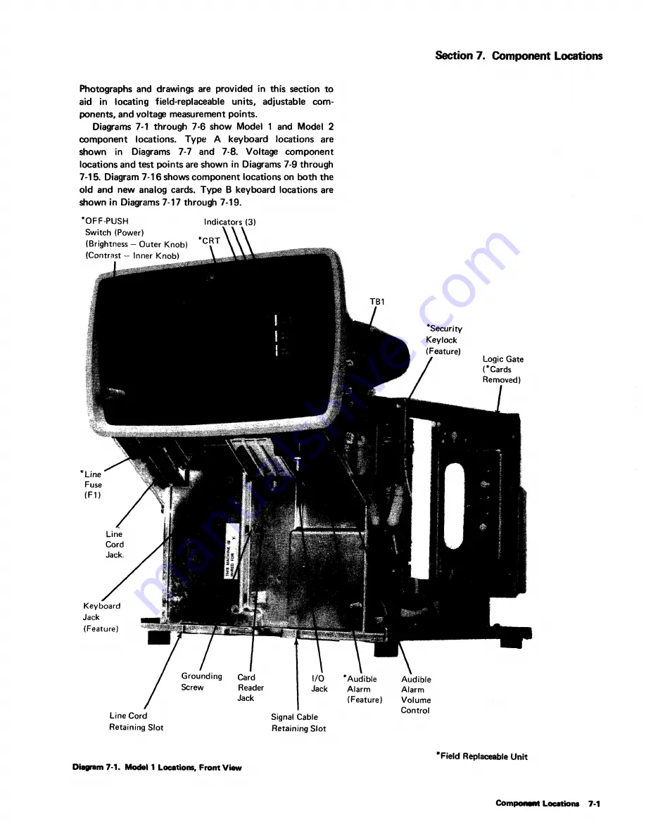
Page 97: ...cations and test points are shown in Diagrams 7 9 through 7 15 Diagram 7 16 shows component locations on both the old and new analog cards Type B keyboard locations are shown in Diagrams 7 17 through 7 19 OFF PUSH Switch Power Brightness Outer Knob Contrast Inner Knob Line Fuse F1 Jack Feature Line Cord Retaining Slot Indicators 3 Reader Jack Jack Signal Cable Retaining Slot Diagram 7 1 Modell Loc...

Page 98: ...s Potentiometer Diagram 7 2 Model 1 Locations Left Side View 7 2 Yoke Shield Yoke under Shield High Voltage Power Supply CRT INTEN CRTPb CRT Anode Prime Power Box 12V Regulator Behind Low Voltage PC Board Slj Analog Card Adjustments 4 Field Replaceable Units ...

Page 99: ... 5V Decoupling Capacitor Diagram 7 3 Model 1 Locations Rear View CRT 12V Regulator Yoke Shield Arc Su ppression Board Cone Shield Field Replaceable Units Component Locations 7 3 ...

Page 100: ... 5V Fuse AI Fl 34V Fuse AI F2 TB1 Diagram 7 3 1 Location of 5V and 34V Fuses Model 1 74 ...

Page 101: ...Cord Jack Line Fuse F1 Grounding Wing Screw Keyboard Audible Audible Jack Alarm Alarm Feature Volume Feature Control O m 7 4 Model 2 Locations Front View Indicators 3 Low Voltage Fuses 3 Under Shield Low Voltage Power Supply Shield PC Board under Shield Field Replaceable Unit Component Locations 7 5 ...

Page 102: ...eplaceable Unit Security Keylock Feature CRT Grounding Spring Lower Chassis Diagram 7 5 Model 2 Locations Right Sicle View 7 6 Centering Magnets 2 Under Shields Chassis Clamp 12V Regulator Logic Board 5V 5V Fuse 01C Fl 34V Fuse 01C F2 ...

Page 103: ...Note This view shows the area to the right and behind the keylock as shown in Diagram 7 5 Diagram 7 5 1 location of 5V and 34V Fuses Model 2 Component Locations 7 7 ...

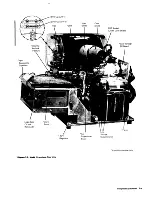
Page 104: ...e Power Supply Upper Chassis Ferro Cover AC Ferro behind Capacitor Cover Diagram 7 6 Model 2 Locations Left 5ide View 7 8 Yoke Shield Yoke under Shield Power Prime Control Power Actuator Box Chassis Clamp CRT Anode CRT Field Replaceable Unit ...

Page 105: ...sHmbly Screw Diagram 7 7 Type A Keyboard Locations Audible Feedback Assembly Top Cover Keyboard As embly Note Either a jumper wIre or a ground strap will be found connecting bottom pan to keyboard assembly Bottom Pan Component Locations 7 9 ...

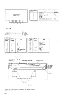
Page 106: ... O Conn 12 4 I O Conn 13 and KBI Z 5 Not Used 6 Not Used 7 Not Used 8 Audible Feedback Assy White wire 9 Audible Feedback Assy Blue wire At Disploy Station I O Conn KBI Conn at Disploy at Signal Station Keybaard 14 T Alpha 15 U DE Up Shift 16 S Numeric 17 P Flip Flop Enable 18 K Bit 5 19 A Spore 20 Not Used Not Used 21 Not Used Not Used 22 C Reset 23 B Spore 24 V and W 8V dc 25 Audible Feedback 8V...

Page 107: ...Prior to EC 717661 34V Return 34V EC 717661 and loter 34V Return Diagram 7 9 Low Voltage Printed Circuit Board 5V 5V Return J2 0 00 12V 3 pins 12V Return 8 pins 18V Return Component Locations 7 1 ...

Page 108: ... z w 0 Q F1 0 2ASB 0C2 2 F2 12V Q SASB REG F3 0 5 2ASB 0 0 I o 34V 0 0 O 8V O 18V Diagram 7 10 Low Voltage Printed Circuit Board Shield Arc Suppression Neon Diegrem 7 11 Model 2 Voltage Distribution Board 7 12 ...

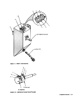
Page 109: ...5 6 3 OFF PUSH Control Shaft Line Fuse FU Diagram 7 12 Modal 1 Prime Power Box c A R2 Brightness D m 7 13 Brlghtneaand Contrast Control Terminals Component Locations 7 13 ...

Page 110: ...7 15 Model 1 Arc suppr ion Board 7 14 Focus Adj Potentiometer o o o o 400V Focus 400V Enable Input uv OC Return Notes 1 Connector pins on reverse side of board 2 Component layout may differ from illustration depending on part number and EC level however connector pins are numbered the same on all variations ...

Page 111: ... Analog Card Sheet 1 of 2 Tnt Poinu WIDTH INTEN CRTPb NIDI 1 IV to Brithtnftl Pot 2 WI Brithtnftl Pot 3 60V erightMss Pot CRTGrid 5 DC Gnd to Audlbl Alerm 6 CRT Cethodt 7 Spere a Vert Skip Bumpl In 9 Sper 10 Vert RmlCl 11 5V in Flit 51 12 Unblank CRT 13 DC Gnd from logic BoIrd 14 Horiz Sync 16 Duel Intensity Britht Normel 16 Audibl Alarm from Logic 17 Wiper of Contrllt Pot 18 Contrllt Pot 19 Audib...

Page 112: ...t Analog 1 Diagram 7 16 Analog Card Sheet 2 of 2 TOP MARGIN WIDTH P4 D 1 8V to Brightness Potentiometer 2 Wiper Brightness Potentiometer 3 60V Brightness Potentiometer 4 CRT Grid 5 DC Gnd to Audible Alarm 6 CRT Cathode 7 Frame Gnd 8 Vert Skip Bump In 9 Spare 10 Vert Retrace 11 5V In Fast 51 12 Unblank CRT 13 DC Gnd from Logic Board 14 Horiz Sync 15 Dual Intensity Bright Normal 16 Audible Alarm fro...

Page 113: ...ctor KBl Captive Screw Cable Assembly Brockel Diagram 7 17 Type B Keyboard Locations Circuit Board and Electronics Assembly Bottom Pan Actuator Mechanism Assembly Audible Feedbock Card Assembly Compo nt Locations 7 17 ...

Page 114: ...pendi ng upon EC Diagram 7 18 Type B Keyboard Assembly 7 18 Keybutton Group Protective Shield Membrane f Spocebar Stabilizer Pivot 2 Key Module Foam Strip 2 t Top Insulator 2 Circuit Board and Electronics Assembly Base Insulator Bose Plate Ground Isolation Insert 6 t Holding Screw 6 ...

Page 115: ...t 6 7 812 Bit 7 8 804 Parity Bit 9 802 Strobe 10 010 Audible Feedback Signal 11 OOS Gnd OV de 12 Audible Feedback Return 13 002 12V de Ground on Typewriter Keyboard Not used on Typewriter Keyboard TEST POINTS 8 0 2 Circuit Board and Electronics Assembly 1 0 Conn at Display Station 14 15 16 17 18 19 20 21 22 23 24 25 KBI Conn at Signal Keyboard DOS AlphCJ Shift 004 DE Up Shift D06 Numeric Shift 011...

Page 116: ...asis COM l00V 110V 123 5V nov 235V 5 o 0 0 Ferro D m 8 1 5O Hz F ro TB 1 Section 8 Installation Instructions 8 2 1 Line Voltage Check Domestic USA models use 115V ac 10 60 Hz single phase line voltage No internal adjustments are required for domestic display stations Important Note A grounded power source must be used World Trade models use 100 110 123 5 220 235V ac 50 Hz single phase or 100V ac 6...

Page 117: ...t cover if it was not previously removed to install feature s 2 Plug line cord into display station chassis jack 8 2 3 Open side covers 4 Inspect for loose cords in logic gate and for loose cable connections 8 2 4 Power On Checks 1 Plug line cord into power source and pull out OFF PUSH switch 2 Perform the display station operational test described in paragraph 5 1 2 beginning at step 3 3 Refer to...

Page 118: ...es 1 fJ08nddlqMlydabisnownbyherlv line 2 eMCMt I2only 3 Keyboard data path when card reeder feature is installed 4 0 Adjustment 6 T Switch Horizonul WIdth CtwlCter Height Horfzonul Otftectlon AmpUfler v Deflettlon Amplif AUdibl A ann dv I AnllogCard Refe ence Data FO ...

Page 119: ...3 Display Station Model 2 Front View 7 5 Diag 7 4 Left 5ide View 7 8 Diag 7 6 Right Side View 7 6 Diag 7 5 Keyboard Type A 7 9 Diag 7 71 7 10 Diag 7 8 Index Type B 7 17 Oia9 7 17 7 18 Diag 7 18 7 19 Diag 7 19 Component Replacement See removal entry for desired component Contrast AdJustment 5 7 Control Unit Addresses 2 9 Diag 2 10 Controls External 6 1 Internal 6 2 Cover Removal Displav Station 5 9...

Page 120: ... Circuit Board Shield 7 12 Diag 7 10 Magnetic Centering Ring Adjustment 3 8 Diag 3 7 5 7 Maintenance Approach 1 2 Diag 1 1 No Horizontal Sync 3 9 Diag 3 15 No Interrow Spacing 3 9 Diag 3 16 X 2 Offline Maintenance 1 1 OF F PUSH Switch Adjustment 5 8 5 9 D iag 5 1 OLTs 2 3 2 8 Online Maintenance 1 1 Operator Identification Card Reader Installation 8 2 Removal 5 20 Test Card 2 3 Tests 5 2 Oscillosco...

Page 121: ...s 1 1 2 1 Top Margin Adjustment 5 8 Trouble Analysis 1 1 Troubleshooting Diagram Usage 4 1 Troubleshooting Diagrams 1 1 4 3 through 4 30 Type A Keyboard Description 5 5 Locations 7 9 Oiag 7 7 7 10 Oiag 7 8 Ttpe B Keyboa d Assembly 1 18 Oiag 1 18 Description 5 5 locations 7 17 Oi8g1 17I 1 18 Oiag 7 181 7 19 Oi89 7 19 Voltage Checks Arc Suppression 5 4 General 5 3 High Voltage k Keyboard 5 5 Low Vol...

Page 122: ...se contactyour IBM representative or the IBM Branch Office servingyour locality Possible topics for comment are Clarity Accuracy Completeness Organization Index Figures Examples Legibility READER S COMMENT FORM What is your occupation _______________________________ Number of latest Technical Newsletter if any concerning this publication _____________ Please indicate if you wish a reply DYes o No ...

Page 123: ... become the property of IBM Fold Fold I Business Reply Mail No postage stamp necessary if mailed in the U S_A Postage will be paid by International Business Machines Corporation Department 52 L Neighborhood Road Kingston New York 12401 First Class Permit 40 Armonk New York I Fold International Business Machines Corporation Data Processing Division 1133 Westchester Avenue White Plains New York 1060...

Page 124: ... u E SY27 2314 5 International Buslne Machine Corporation Data Proce lng Division 1133 Westchester Avenue White Plains New York 10604 U S A only IBM World Trade Corporation 821 United Nations Plaza New York New York 10017 lntematlonal ...

Reviews: