background image

Chapter 1. Introduction

The IBM LTO Ultrium 5 Half High Tape Drive is a high-performance,
high-capacity data-storage device that is designed to backup and restore
open-systems applications. The tape drive is available as an internal or external
device (L5X and N5X models). The L5X model of the tape drive includes a power
cord for use in the United States; the N5X model does not include a power cord.

The IBM LTO Ultrium 5 Half High Tape Drive is the fifth generation in the
Ultrium series of products, and is available with a Serial Attached SCSI interface
(SAS). This model incorporates the Linear Tape-Open (LTO) IBM Ultrium 5 Half
High Tape Drive.

Read this entire document and the IBM Safety, Warranty, Environmental, and
Electronic Emission Notices document that comes with the drive before you install
or use the drive.

The Customer Replaceable Unit (CRU) part numbers and the Option part numbers
for the IBM LTO 5 Half High Tape Drive are shown in the following list:

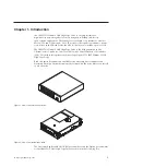
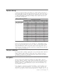
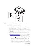
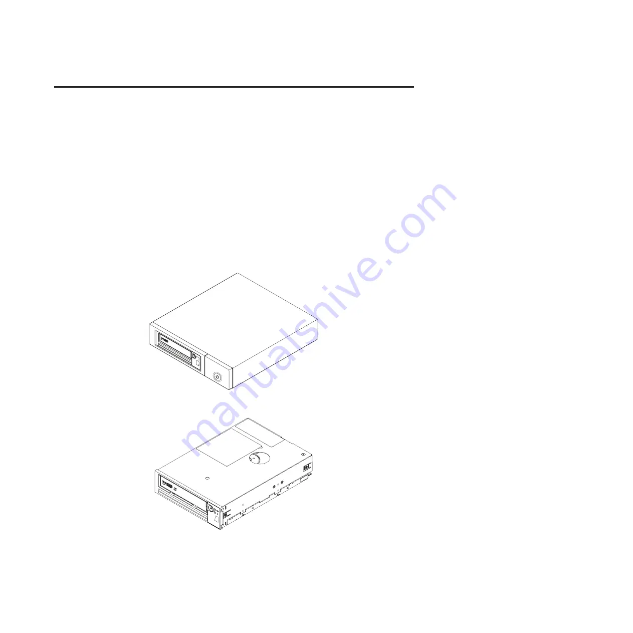
Figure 1. View of an external tape drive

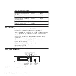
Figure 2. View of an internal tape drive

© Copyright IBM Corp. 2011

1

Summary of Contents for 3628

Page 1: ...ortant Review the maintenance information in Chapter 3 Operating the drive and in the Warranty information document that comes with the tape drive because periodic maintenance is not covered by the IBM warranty Repairs or exchanges that result from improper maintenance might result in billable service charges ...

Page 2: ......

Page 3: ...IBM Half High LTO Gen 5 SAS Tape Drive Installation and User s Guide Machine Type 3628 Model L5X and N5X ...

Page 4: ...ion and Environmental Notices and User Guide documents on the IBM Documentation CD and the Warranty information and Important notices documents that come with the product First Edition May 2011 Copyright IBM Corporation 2011 US Government Users Restricted Rights Use duplication or disclosure restricted by GSA ADP Schedule Contract with IBM Corp ...

Page 5: ...kt Lees voordat u dit product installeert eerst de veiligheidsvoorschriften Ennen kuin asennat tämän tuotteen lue turvaohjeet kohdasta Safety Information Avant d installer ce produit lisez les consignes de sécurité Vor der Installation dieses Produkts die Sicherheitshinweise lesen Prima di installare questo prodotto leggere le Informazioni sulla Sicurezza Les sikkerhetsinformasjonen Safety Informa...

Page 6: ...leia as Informações sobre Segurança Antes de instalar este producto lea la información de seguridad Läs säkerhetsinformationen innan du installerar den här produkten iv Half High LTO Gen 5 SAS Tape Drive Installation and User s Guide ...

Page 7: ... equipment when there is evidence of fire water or structural damage v Disconnect the attached power cords telecommunications systems networks and modems before you open the device covers unless instructed otherwise in the installation and configuration procedures v Connect and disconnect cables as described in the following table when installing moving or opening covers on this product or attache...

Page 8: ...osure DANGER Some laser products contain an embedded Class 3A or Class 3B laser diode Note the following Laser radiation when open Do not stare into the beam do not view directly with optical instruments and avoid direct exposure to the beam Statement 5 CAUTION The power control button on the device and the power switch on the power supply do not turn off the electrical current supplied to the dev...

Page 9: ...as the following label attached Hazardous voltage current and energy levels are present inside any component that has this label attached There are no serviceable parts inside these components If you suspect a problem with one of these parts contact a service technician Safety vii ...

Page 10: ...viii Half High LTO Gen 5 SAS Tape Drive Installation and User s Guide ...

Page 11: ...g a tape cartridge 22 Mid tape recovery 22 Cleaning the drive head 23 Cleaning the tape drive 23 Diagnostic and maintenance functions 23 Entering Maintenance mode 25 Exiting Maintenance mode 25 Function code 0 Maintenance mode 26 Function code 1 Run drive diagnostics 26 Function code 2 Update drive firmware from FMR tape 27 Function code 3 Create FMR tape 28 Function code 4 Force a drive dump 28 F...

Page 12: ...ndix F Notices 77 Trademarks 77 Important notes 78 Particulate contamination 79 Documentation format 79 Electronic emission notices 80 Federal Communications Commission FCC statement 80 Industry Canada Class A emission compliance statement 80 Avis de conformité à la réglementation d Industrie Canada 80 Australia and New Zealand Class A statement 80 European Union EMC Directive conformance statemen...

Page 13: ...Double boxing tape cartridges for shipping 47 13 Flowchart for analyzing maintenance problems 49 14 RID tag on rear panel 53 15 Leader pin in the incorrect and correct positions 66 16 Placing the dislodged leader pin into the correct position 66 17 Rewinding the tape into the cartridge 67 18 Leader Pin Reattachment Kit 68 19 Attaching the leader pin attach tool to the cartridge 69 20 Winding the t...

Page 14: ...xii Half High LTO Gen 5 SAS Tape Drive Installation and User s Guide ...

Page 15: ...g of status lights and single character display SCD 18 7 Functions that the Unload button performs 20 8 Diagnostic and maintenance functions 24 9 Ultrium cartridge compatibility with Ultrium tape drives 44 10 Environment for operating storing and shipping LTO media 47 11 CRU and Option part numbers 52 12 Error codes on the SCD 59 13 Limits for particulates and gases 79 Copyright IBM Corp 2011 xiii...

Page 16: ...xiv Half High LTO Gen 5 SAS Tape Drive Installation and User s Guide ...

Page 17: ...es Chapter 5 Resolving problems on page 49 gives tips for solving tape drive problems Appendix A Getting help and technical assistance describes what to do if you experience a problem with your tape drive and might help you determine whom to call for service if it is necessary Appendix B TapeAlert flags on page 57 lists TapeAlert messages that are supported and that might help you determine the ca...

Page 18: ...tion These statements indicate situations that can be potentially hazardous to you A caution statement is placed just before the description of a potentially hazardous procedure step or situation v Danger These statements indicate situations that can be potentially lethal or extremely hazardous to you A danger statement is placed just before the description of a potentially lethal or extremely haz...

Page 19: ...e Drive is the fifth generation in the Ultrium series of products and is available with a Serial Attached SCSI interface SAS This model incorporates the Linear Tape Open LTO IBM Ultrium 5 Half High Tape Drive Read this entire document and the IBM Safety Warranty Environmental and Electronic Emission Notices document that comes with the drive before you install or use the drive The Customer Replace...

Page 20: ...Systems interface SAS Note Although the tape drive has two SAS ports the drive supports only one host connection The Ethernet port is only used by service personnel v Half height form factor v Native storage capacity of 1 500 GB 1 5 TB per cartridge 3 000 GB at 2 1 compression v Maximum native data transfer rate of up to 140 MB per second v Burst data transfer rate of 600 MB per second v 256 MB re...

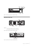
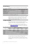
Page 21: ...rnal tape drive front panel element descriptions Important 1 The tape drive supports only one host connection 2 The Ethernet port is only used by service personnel Figure 5 External tape drive rear panel element descriptions SAS and power cable connector Fan Figure 6 Internal tape drive rear panel element descriptions Chapter 1 Product description 3 ...

Page 22: ...rtridge and is compatible with the cartridges of its predecessor the IBM Half High LTO Ultrium 4 Tape Drive The drive has the following capabilities and limitations Note To improve system performance the drive uses a feature called speed matching to dynamically adjust its native uncompressed data rate to the slower data rate of a server For more information about speed matching see Speed matching ...

Page 23: ... reduces backhitch the condition that occurs when a tape stops reverses and restarts motion A backhitch is usually the result of a mismatch between the data rates of the server and the drive Channel calibration System performance is further optimized by a channel calibration feature With this feature the drive automatically customizes each read or write data channel to compensate for variations in...

Page 24: ...ted simultaneously with thinner and longer cables its full duplex signal transmission supports 6 0 Gb second SAS drives can be hot plugged SAS drives will auto negotiate speed There are no configurable topologies and therefore no feature switches associated with SAS Supported servers and operating systems To determine the latest supported attachments visit the IBM ServerProven website for System x...

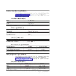
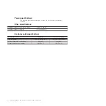
Page 25: ...3 048 m 10 000 ft Maximum altitude for shipping 12 192 m 40 000 ft Environmental specifications Environmental factor Operating Storage or Shipping Drive temperature 10 to 40 C 50 to 104 F 40 to 60 C 40 to 140 F Relative humidity noncondensing 20 to 80 10 to 90 Wet bulb temperature maximum 26 C 78 8 F 26 C 78 8 F Internal tape drive specifications The following sections show the physical power and ...

Page 26: ...8 m 10 000 ft Maximum altitude for shipping 12 192 m 40 000 ft Environmental specifications Environmental factor Operating Storage or Shipping Drive temperature 10 to 40 C 50 to 104 F 40 to 60 C 40 to 140 F Relative humidity noncondensing 20 to 80 10 to 90 Wet bulb temperature maximum 26 C 78 8 F 26 C 78 8 F 8 Half High LTO Gen 5 SAS Tape Drive Installation and User s Guide ...

Page 27: ...ce removed covers and other parts in a safe place v Do not attempt to lift an object that you think is too heavy for you If you have to lift a heavy object observe the following precautions Make sure that you can stand safely without slipping Distribute the weight of the object equally between your feet Use a slow lifting force Never move suddenly or twist when you lift a heavy object To avoid str...

Page 28: ...ser s Guide this document the multilingual Safety Information document and the Environmental Notices and User s Guide v SAS cable An internal split SAS cable for the internal drive An external SAS cable for the external drive v Mounting screws internal drive only and are not used for installations in servers that come with mounting rails Installing an internal tape drive Use the information in thi...

Page 29: ...rive has cooled to the operating temperature range less than 40 C or 104 F cool the drive more quickly by applying airflow for 30 minutes Power on the drive and use a diagnostic tape to test it before inserting a tape that contains data If you are uncertain about whether the temperature of the drive is within the recommended operating range or the humidity is sufficient to cause condensation accli...

Page 30: ... report the permanent error instead of activating the head brush ERP Mount the drive in an enclosure or server When mounting the drive v Use an appropriate screw length v Make sure that no objects such as screw heads cables or adjacent devices are pressing against the frame v Do not obstruct the ventilation slots at the rear of the drive v Allow sufficient space for accessing the drive s front pan...

Page 31: ...ile turning on the power to the enclosure v During the power on initialization and POST Power On Self Test the SCD briefly displays 8 then becomes blank not lit when POST is complete and there are no POST errors If a POST error has been detected an error code will be displayed in the SCD and the status LED will flash amber Attention If the SCD does not come on the drive might not be getting power ...

Page 32: ...rs on the single character display SCD go to Appendix C Error codes and messages on page 59 If no error appears continue to the next step 5 Turn off the enclosure 6 Disconnect the power cord from both the enclosure and the electrical outlet Install device drivers If you intend to use the tape drive with a commercial software application see the documentation for that application to install the dev...

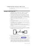
Page 33: ...e length of the power cord and the length of the cable to the server Do not place anything on top of the tape drive 7 If there are no other devices attached to your server a SAS host adapter card might need to be installed in the server To install an adapter see the instructions that accompany it as well as the documentation that came with your server 8 Locate the SAS cable and make sure the tape ...

Page 34: ...stems support supportsite wss docdisplay lndocid TAPE FILES brandind 5000019 or complete the following steps Note Changes are made periodically to the IBM website The actual procedure might vary slightly from what is described in this document 1 Go to http www 947 ibm com support entry portal 2 In the Search within all of support downloads text field at the bottom of the screen type tape files and...

Page 35: ...gle character display SCD The SCD see Front panel of the drive on page 2 presents a single character code for v Error conditions and informational messages v Diagnostic or maintenance functions in Maintenance mode only Appendix C Error codes and messages on page 59 lists the codes for error conditions and informational messages If multiple errors occur the code with the highest priority represente...

Page 36: ...uting maintenance selection Flashing character Off On Error condition Solid character Off Flashing Power is turned on or a reset is initiated Random segments Off On Note The white Encryption status light will be on when the tape drive has a cartridge loaded and all data on this cartridge is encrypted This applies only to LTO Ultrium 5 cartridges Table 6 lists the conditions of the status lights an...

Page 37: ...og on the SCD For more information see Function code 9 Display error code log on page 32 and Appendix C Error codes and messages on page 59 On or off On or off Off Displaying random segments then blank then displaying random segments then displaying 8 then blank Off During power on or a drive reset the drive front panel will display drive progress as follows 1 SCD will display random segments no L...

Page 38: ...is a drive dump in flash memory 1 Power should not be disconnected from the drive until the microcode update is complete The drive indicates that the update is complete by resetting and performing POST Unload button The Unload button see Front panel of the drive on page 2 performs the following functions Table 7 Functions that the Unload button performs Unload button function How to initiate the f...

Page 39: ...status light is flashing and fault light is solid see Function code 4 Force a drive dump on page 28 v If the drive is in Operating mode status light is solid or flashing green press and hold the Unload button for ten seconds If a captured dump data exists the drive places it into a dump area Reset the drive Press and hold the Unload button until the drive begins the reset procedure status light wi...

Page 40: ...rtially ejects grasp the cartridge and remove it Important Always remove an ejected cartridge before reinserting it Whenever you unload a tape cartridge the drive writes any pertinent information to the cartridge memory Mid tape recovery If the tape drive is reset while a cartridge is loaded the drive will slowly rewind the tape and eject the cartridge If the drive power is turned off and then on ...

Page 41: ...for 50 uses Cleaning the tape drive Clean the exterior surface of the tape drive with a damp towel If you use a liquid all purpose cleaner apply it to the towel Do not spray cleaner directly on the tape drive Diagnostic and maintenance functions The drive is capable of the following v Run diagnostics v Test write and read functions v Test a suspect tape cartridge v Update firmware v Perform other ...

Page 42: ... the RS 422 interface Function code 7 Run RS 422 wrap test on page 31 8 Unmake FMR Tape Erases the FMR data on a customer supplied scratch blank data cartridge and rewrite the cartridge memory on the tape This turns the cartridge into a valid customer supplied scratch data cartridge Function code 8 Unmake FMR tape on page 32 9 Display Error Code Log Displays the last 10 error codes one at a time T...

Page 43: ...the preceding step While in Maintenance mode the drive will not accept a cartridge unless the drive requests it The SCD will display a flashing C to indicate a cartridge needs to be inserted Maintenance functions cannot be performed concurrently with read or write operations While in Maintenance mode the drive does not acknowledge SCSI commands from the server Exiting Maintenance mode The drive mu...

Page 44: ... Approximate Run Time run Function code F Write performance test on page 34 If the Write performance test fails replace the media and exit Maintenance mode Attention For this test insert only a scratch blank data cartridge or a cartridge that can be overwritten During the test the drive overwrites the data on the cartridge Note If you inserted an invalid tape cartridge for example Gen 2 or WORM me...

Page 45: ... drive firmware from FMR tape complete the following steps 1 Put the drive in Maintenance mode For instructions see Entering Maintenance mode on page 25 2 Press the Unload button once per second until 8 appears in the SCD If you cycle past the desired code press the Unload button once per second until the code reappears 3 Press and hold the Unload button for three or more seconds then release it t...

Page 46: ... until the code reappears 3 Press and hold the Unload button for 3 or more seconds then release it to select the function The SCD changes to a flashing C 4 Insert a scratch blank data cartridge that is not write protected or the tape drive exits maintenance mode The SCD changes to a flashing 3 The tape drive copies the FMR data to the scratch data cartridge v If the tape drive creates the FMR tape...

Page 47: ...d only compatibility for example Gen 3 media error code P appears in the SCD In either case the tape drive unloads the cartridge and exits Maintenance mode after the cartridge is removed To execute Function code 5 Copy drive dump complete the following steps 1 Put the drive in Maintenance mode For instructions see Entering Maintenance mode on page 25 Index through the Maintenance mode options unti...

Page 48: ...terface wrap test Approximate Run Time 10 seconds per loop Number of Loops This test runs until stopped by pressing the Unload button Function code 6 performs a check of the host interface circuitry and host connector on the drive To execute Function code 6 Run host interface wrap test 1 Make sure that the host interface wrap plug is connected to the host interface connector at the rear of the dri...

Page 49: ... of the circuitry and connector for the RS 422 interface This connector supports the Library Drive Interface LDI and the Automation Drive Interface ADI Before selecting this function attach an LDI or RS 422 wrap plug to the drive LDI or RS 422 connector in place of the LDI or RS 422 cable 1 Make sure that no cartridge is in the drive and the correct wrap plug is attached to the RS 422 connector 2 ...

Page 50: ...f you inserted a write protected cartridge or the media has read only compatibility for example Gen 3 media error code P appears in the SCD In either case the tape drive unloads the cartridge and exits Maintenance mode after the cartridge is removed Function code 9 Display error code log Function code 9 displays the last 10 error codes one at a time The codes are ordered the most recent is present...

Page 51: ...e drive diagnostics and Create FMR tape that require a tape cartridge to be inserted Function code E Test cartridge media Approximate Run Time 15 minutes per loop Total Number of Loops 10 Function code E performs tests that determine whether a suspect cartridge and its magnetic tape are acceptable Press the Unload button to stop the diagnostic and exit Maintenance mode Press the Unload button once...

Page 52: ...ding the Unload button for 10 seconds Function code F Write performance test Approximate Run Time 5 minutes per loop Total Number of Loops 10 Function code F performs tests to make sure that the drive can read from and write to tape Press the Unload button to stop the diagnostic and exit Maintenance mode Press the Unload button once to abort the test at the end of the current test loop Press the U...

Page 53: ...he diagnostic begins the loop sequence Time the first loop by pressing the Unload button once to stop the diagnostic after the completion of the first loop then record the time it takes for the test to complete Compare the recorded time with the Approximate Run Time above If the test runs successfully but the execution time is significantly longer than the Approximate Run Time run Function code F ...

Page 54: ...r of Loops 10 Function code J performs tests to make sure that the drive can read from and write to tape Once you begin this test the diagnostic begins the loop sequence Time the first loop by pressing the Unload button once to stop the diagnostic after the completion of the first loop then record the time it takes for the test to complete Compare the recorded time with the Approximate Run Time ab...

Page 55: ...te the code in Appendix C Error codes and messages on page 59 To clear the error either turn the power off and then on again or restart the drive by pressing and holding the Unload button for 10 seconds Function code L Load unload test Approximate Run Time 15 seconds per loop Total Number of Loops 10 Function code L tests the ability of the drive to load and unload a tape cartridge Press the Unloa...

Page 56: ...e on page 25 2 Press the Unload button once per second until either P or U appears in the SCD P or U will appear in the SCD to indicate the current setting for post error reporting If you cycle past the desired code press the Unload button once per second until the code reappears 3 Exit Maintenance mode if you do not want to change the current setting for post error reporting For instructions see ...

Page 57: ...er second until the code reappears 3 Exit Maintenance mode if you do not want to change the current setting for post error reporting For instructions see Exiting Maintenance mode on page 25 4 To disable post error reporting press and hold the Unload button for 3 seconds while P appears in the SCD The SCD changes to U after you release the Unload button 5 Press the Unload button once per second to ...

Page 58: ...40 Half High LTO Gen 5 SAS Tape Drive Installation and User s Guide ...

Page 59: ...cartridge is out of the drive Leader pin The tape is attached to a leader pin behind the cartridge door When the cartridge is inserted into the drive a threading mechanism pulls the pin and tape out of the cartridge across the drive head and onto a take up reel The head can then read or write data from or to the tape Write protect switch This switch prevents data from being written to the tape car...

Page 60: ... of IBM LTO Ultrium data cartridges include a Linear Tape Open Cartridge Memory LTO CM chip see Figure 9 on page 41 that contains information about the cartridge and the tape such as the name of the manufacturer that created the tape as well as statistical information about the cartridge use The LTO CM enhances the efficiency of the cartridge For example the LTO CM stores the end of data location ...

Page 61: ...tracks at a time Ultrium 4 WORM Green and silvery gray 800 GB 1 600 GB at 2 1 compression Reads and writes data on 896 tracks 16 tracks at a time Ultrium 3 WORM Slate blue and silvery gray 400 GB 800 GB at 2 1 compression Reads and writes data on 704 tracks 16 tracks at a time 1 The first set of tracks which is 16 for Ultrium 5 4 and 3 cartridges is written from near the beginning of the tape to n...

Page 62: ... the head insert the cleaning cartridge into the tape load compartment of the drive The cleaning is performed automatically When the cleaning is finished the cartridge is ejected Note The drive will automatically eject an expired cleaning cartridge IBM cleaning cartridges are valid for 50 uses The cartridge LTO CM chip tracks the number of times that the cartridge is used Cartridge compatibility T...

Page 63: ...t exist near high current cables or power supplies Such exposure can cause the loss of recorded data or make the blank cartridge unusable v Maintain the conditions that are described in Environmental and shipping specifications for tape cartridges on page 47 Inspect the cartridge Before using the cartridge perform the following steps v Inspect the cartridge packaging to determine potential rough h...

Page 64: ...nly a recommended shipping container that holds the cartridge securely in its jewel case during transportation Ultrium Turtlecases by Perm A Store have been tested and found to be satisfactory They are available at http www turtlecase com v Never ship a cartridge in a commercial shipping envelope Always place it in a box or package v If you ship the cartridge in a cardboard box or a box of a sturd...

Page 65: ...rating storing and shipping LTO media Environmental specifications Environmental factor Operating Operational storage1 Archival storage2 Shipping Temperature 10 to 45 C 50 to 113 F 16 to 32 C 61 to 90 F 16 to 25 C 61 to 77 F 23 to 49 C 9 to 120 F Relative humidity non condensing 10 to 80 20 to 80 20 to 50 5 to 80 Maximum wet bulb temperature 26 C 79 F 26 C 79 F 26 C 79 F 26 C 79 F 1 The short term...

Page 66: ... use a minimum of 4000 oersted peak field over the entire space that the cartridge occupies The tape should make two passes through the field at 90 degree orientation change for each pass to achieve complete erasure Some commercial degaussers have two magnetic field regions offset 90 degrees from each other to accomplish complete erasure in one pass for higher throughput Degaussing makes the cartr...

Page 67: ... and the drive is functioning properly refer to Procedure 3 in this chapter Refer to Appendix A in this document before you call IBM Technical Support Then contact IBM Technical Support 1 Refer to the section about codes on the single character display in this guide 2 Ensure that the latest level of firmware is installed on the drive refer to Procedure 1 in this chapter 3 Refer to Appendix A in th...

Page 68: ...our System x hardware and options go to http www 03 ibm com systems info x86servers serverproven compat us indexsp html To check the host connections for your drive complete the following steps 1 Make sure that the tape drive power is on 2 Make sure that the SAS cable is fully seated in the server and in the tape drive 3 Make sure that the parameters for the SAS host adapter installation are corre...

Page 69: ...ated in the server and the tape drive 3 Replace the SAS cable if it shows any signs of damage Resolving problems with the tape media To resolve problems that are related to media the drive firmware includes the following capabilities v Test Cartridge Media diagnostic that verifies whether a suspect cartridge and its magnetic tape are acceptable for use v Statistical Analysis and Reporting System S...

Page 70: ...ternal Half High LTO Gen 5 SAS Drive with no line cord 49Y9907 3628N5X SAS cable internal 44E8878 Mini SAS cable external 3 m x 4 plug 39R6532 US line cord 3 ft 10 A 125 V 39M5081 To replace your tape drive complete the following steps 1 Remove the replacement unit from its packaging 2 Locate the repair identification RID tag that is included with the replacement unit See Figure 14 on page 53 3 Wr...

Page 71: ...Figure 14 RID tag on rear panel Chapter 5 Resolving problems 53 ...

Page 72: ...54 Half High LTO Gen 5 SAS Tape Drive Installation and User s Guide ...

Page 73: ... by following the troubleshooting procedures that IBM provides in the online help or in the documentation that is provided with your IBM product The documentation that comes with IBM systems also describes the diagnostic tests that you can perform Most systems operating systems and programs come with documentation that contains troubleshooting procedures and explanations of error messages and erro...

Page 74: ...or region see http www ibm com services supline products For more information about Support Line and other IBM services see http www ibm com services or see http www ibm com planetwide for support telephone numbers In the U S and Canada call 1 800 IBM SERV 1 800 426 7378 Hardware service and support You can receive hardware service through your IBM reseller or IBM Services To locate a reseller aut...

Page 75: ... server to read TapeAlert flags from a tape drive through the host interface The server reads the flags from Log Sense Page 0x2E See the IBM LTO Ultrium Tape Drive SCSI Reference document for the list of TapeAlert flags that are supported by this tape drive To download the IBM LTO Ultrium Tape Drive SCSI Reference document PDF go to http www 01 ibm com support docview wss uid ssg1S7001045 aid 1 Co...

Page 76: ...58 Half High LTO Gen 5 SAS Tape Drive Installation and User s Guide ...

Page 77: ...temperature was exceeded Perform one or more of the following actions v Make sure that the cooling fan is rotating and is quiet If it is not see the documentation that came with your enclosure v Remove any blockage that prevents air from flowing freely through the tape drive v Make sure that the operating temperature and airflow is within the specified range see External tape drive specifications ...

Page 78: ... drive to copy and read a drive dump use Function code 5 Copy drive dump on page 29 2 Turn the tape drive power off and on then retry the operation that produced the error The error code clears when you place the tape drive in Maintenance mode 3 If the problem persists download new firmware and retry the operation if new firmware is not available replace the drive 5 Tape drive hardware problem The...

Page 79: ...d on page 35 If the diagnostic fails replace the tape drive If the diagnostic succeeds replace the cartridges that caused the problem The error code clears when you remove the tape cartridge or place the tape drive in Maintenance mode For Problems with Reading Data If the problem occurred while the tape drive was reading data from the tape perform one of the following procedures v If another tape ...

Page 80: ...verwritten Use only a scratch data cartridge to run the test v If the diagnostic fails replace the media v If the diagnostic succeeds clean the drive head see Cleaning the drive head on page 23 and run Function code 1 Run drive diagnostics on page 26 If the drive diagnostic fails replace the drive If the drive diagnostic succeeds perform the operation that produced the initial media error The erro...

Page 81: ... significantly longer than the Approximate Run Time run Function code F Write performance test on page 34 If the Write performance test fails replace the media and exit Maintenance mode If the drive diagnostics run successfully perform the operation that produced the initial drive error 3 If the problem persists replace the drive If it is not possible to run the tape cartridge in a different drive...

Page 82: ...e that the correct media is being used Data encryption is supported with LTO Ultrium 4 and 5 data cartridges only v Retry the encryption operation with the tape cartridge in another encryption enabled drive Replace the media if the problem repeats with the same tape cartridge in multiple drives If the problem occurred while the tape drive was running POST or diagnostics replace the drive The error...

Page 83: ...g steps 1 Look for signs of cartridge mishandling 2 Use the IBM Leader Pin Reattachment Kit part number 08L9129 to correctly seat the pin 3 Use data recovery procedures to minimize the chance of data loss 4 Review the media handling procedures Example Improper placement of the leader pin see Figure 15 on page 66 The leader pin is misaligned Complete the following steps 1 Look for cartridge damage ...

Page 84: ... the pin retaining spring clips 3 Press the leader pin gently into the clips until it snaps into place and is firmly seated 4 Close the cartridge door 5 Make sure that there are no gaps in the seam of the cartridge Figure 16 Placing the dislodged leader pin into the correct position Figure 15 Leader pin in the incorrect and correct positions The cartridge door is open and the leader pin is visible...

Page 85: ...or possible data recovery Discard the mishandled cartridge Figure 17 Rewinding the tape into the cartridge Reattaching a leader pin The first meter of tape in a cartridge is leader tape Once the leader tape is removed the likelihood of tape breakage is increased After reattaching the leader pin transfer data from the defective tape cartridge Important Do not reattach the pin if you must remove mor...

Page 86: ... door open Cartridge manual rewind tool A device that fits into the cartridge hub and lets you wind the tape into and out of the cartridge Leader pins Extra leader pins are included C clips Extra C clips are included Figure 18 Leader Pin Reattachment Kit 68 Half High LTO Gen 5 SAS Tape Drive Installation and User s Guide ...

Page 87: ...rocedure might affect the performance of the leader pin during threading and unloading operations v Touch only the end of the tape Touching the tape in an area other than the end can damage the tape surface or edges which might interfere with read or write reliability To reattach a leader pin by using the IBM Leader Pin Reattachment Kit see Figure 19 and perform the steps below 1 Attach the leader...

Page 88: ...artridge door If necessary grasp the tape and pull gently to unwind it from the cartridge 5 Remove the rewind tool by pulling it away from the cartridge Set the tool and the cartridge aside Figure 20 Winding the tape out of the cartridge To remove the C clip from the leader pin see Figure 21 and complete the following steps 1 On the leader pin locate the open side of the C clip The C clip is a sma...

Page 89: ...tape on the pin will cause the repaired cartridge to fail When the tape is properly centered a 0 25 mm 0 01 in gap exists on both sides of the pin 5 Close the pivot arm of the leader pin attach tool by swinging it over the leader pin so that the C clip snaps onto the pin and the tape 6 Swing the pivot arm open and trim the excess tape so that it is flush with the reattached leader pin 7 Use your f...

Page 90: ...72 Half High LTO Gen 5 SAS Tape Drive Installation and User s Guide ...

Page 91: ...oval procedures vary depending on the type of enclosure The following procedure can be used if the enclosure documentation is not available for the specific enclosure type Removing the internal drive This procedure is to be performed only by IBM Service Personnel Note One of the four screws securing the cover to the chassis is a tamperproof screw A T20 Torx tamperproof screwdriver is required to r...

Page 92: ... Gently push on the rear panel of the drive to remove the chassis from the cover see Figure 24 on page 75 Figure 23 Removing the screws that secure the cover and internal drive 74 Half High LTO Gen 5 SAS Tape Drive Installation and User s Guide ...

Page 93: ... SAS interface and electrical power from the drive Attention Do not disconnect the internal power cable 2 Press the latch assembly to release the drive 3 Slide the internal drive forward toward the front of the chassis to clear the front bezel Figure 24 Removing cables from the internal drive Figure 25 Releasing the drive from the chassis Appendix E Information for trained service personnel 75 ...

Page 94: ...Figure 26 Sliding the drive forward 76 Half High LTO Gen 5 SAS Tape Drive Installation and User s Guide ...

Page 95: ...ABILITY OR FITNESS FOR A PARTICULAR PURPOSE Some states do not allow disclaimer of express or implied warranties in certain transactions therefore this statement may not apply to you This information could include technical inaccuracies or typographical errors Changes are periodically made to the information herein these changes will be incorporated in new editions of the publication IBM may make ...

Page 96: ...rvice marks of others Important notes Processor speed indicates the internal clock speed of the microprocessor other factors also affect application performance CD or DVD drive speed is the variable read rate Actual speeds vary and are often less than the possible maximum When referring to processor storage real and virtual storage or channel volume KB stands for 1024 bytes MB stands for 1 048 576...

Page 97: ...implementation of appropriate remedial measures to mitigate such environmental contamination Implementation of such remedial measures is a customer responsibility Table 13 Limits for particulates and gases Contaminant Limits Particulate v The room air must be continuously filtered with 40 atmospheric dust spot efficiency MERV 9 according to ASHRAE Standard 52 21 v Air that enters a data center mus...

Page 98: ...cables and connectors must be used in order to meet FCC emission limits IBM is not responsible for any radio or television interference caused by using other than recommended cables and connectors or by unauthorized changes or modifications to this equipment Unauthorized changes or modifications could void the user s authority to operate the equipment This device complies with Part 15 of the FCC R...

Page 99: ...zustellen sind die Geräte wie in den Handbüchern beschrieben zu installieren und zu betreiben Des Weiteren dürfen auch nur von der IBM empfohlene Kabel angeschlossen werden IBM übernimmt keine Verantwortung für die Einhaltung der Schutzanforderungen wenn das Produkt ohne Zustimmung der IBM verändert bzw wenn Erweiterungskomponenten von Fremdherstellern ohne Empfehlung der IBM gesteckt eingebaut we...

Page 100: ...of the Voluntary Control Council for Interference VCCI If this equipment is used in a domestic environment radio interference may occur in which case the user may be required to take corrective actions Japan Electronics and Information Technology Industries Association JEITA statement Japanese Electronics and Information Technology Industries Association JEITA Confirmed Harmonics Guideline product...

Page 101: ...Russia Electromagnetic Interference EMI Class A statement People s Republic of China Class A electronic emission statement Taiwan Class A compliance statement Appendix F Notices 83 ...

Page 102: ...84 Half High LTO Gen 5 SAS Tape Drive Installation and User s Guide ...

Page 103: ...of the UNIX operating system The RS 6000 system among others uses AIX as it s operating system alphanumeric Pertaining to a character set that contains letters numerals and usually other characters such as punctuation marks alter To change ambient temperature The temperature of air or other media in a designated area particularly the area surrounding equipment ampere A A unit of measure for electr...

Page 104: ...g them into either the ASCII or EBCDIC digital character code bezel Decorative and safety cover bicolored Having two colors bit Either of the digits 0 or 1 when used in the binary numbering system BM or bill of materials A list of specific types and amounts of direct materials expected to be used to produce a given job or quantity of output browser A client program that initiates requests to a Web...

Page 105: ...pe drive Contrast with data cartridge command A control signal that initiates an action or the start of a sequence of actions compact disc CD A disc usually 4 75 inches in diameter from which data is read optically by means of a laser compression The process of eliminating gaps empty fields redundancies and unnecessary data to shorten the length of records or blocks concurrent Refers to diagnostic...

Page 106: ...y of output or throughput or increased machine error rate deserialize To change from serial by bit to parallel by byte detented A part being held in position with a catch or lever device Any hardware component or peripheral such as a tape drive or tape library that can receive and send data device driver A file that contains the code needed to use an attached device DIAG Diagnostic section of main...

Page 107: ...il Correspondence in the form of messages transmitted between user terminals over a computer network e mail See electronic mail EPO Emergency power off EPROM Erasable programmable read only memory EQC Equipment check equipment check An asynchronous indication of a malfunction Error log A dataset or file in a product or system where error information is stored for later access ESD Electrostatic dis...

Page 108: ...ium and more adaptable to change than pure hardware circuitry An example of firmware is the Basic Input Output System BIOS in read only memory ROM on a PC motherboard FLASH EEPROM An electrically erasable programmable read only memory EEPROM that can be updated FMR Field microcode replacement format The arrangement or layout of data on a data medium formatter Part of a magnetic tape subsystem that...

Page 109: ...e ID Identifier identifier ID 1 In programming languages a lexical unit that names a language object for example the names of variables arrays records labels or procedures An identifier usually consists of a letter optionally followed by letters digits or other characters 2 One or more characters used to identify or name data element and possibly to indicate certain properties of that data element...

Page 110: ...y enables compatibility between different vendors offerings by ensuring that vendors comply with verification standards The LTO technology is implemented in two formats the Accelis format focuses on fast access the Ultrium format focuses on high capacity The Ultrium format is the preferred format when capacity rather than fast access is the key storage consideration An Ultrium cartridge has a comp...

Page 111: ...it is the first generation of its type mega One million of meter In the Metric System the basic unit of length equal to approximately 39 37 inches micro One millionth of microcode 1 One or more micro instructions 2 A code representing the instructions of an instruction set implemented in a part of storage that is not program addressable 3 To design write and test one or more micro instructions 4 S...

Page 112: ...is the magnetic field strength in the interior of an elongated uniformly wound solenoid that is excited with a linear current density in its winding of one abampere per 4π centimeters of axial length offline Pertaining to the operation of a functional unit without the continual control of a computer Contrast with online online Pertaining to the operation of a functional unit that is under the cont...

Page 113: ...downloaded at no cost from the Adobe Systems home page PROM Programmable read only memory PS Power supply PWR Power R rack A unit that houses the components of a storage subsystem such as the library rackmount kit A packaged collection of articles used to install the rack mounted version of the library RAM Random access memory Random access memory A storage device into which data is entered and fr...

Page 114: ... signals represents mechanical motion Small Computer Systems Interface SCSI A standard used by computer manufacturers for attaching peripheral devices such as tape drives hard disks CD ROM players printers and scanners to computers servers Pronounced scuzzy Variations of the SCSI interface provide for faster data transmission rates than standard serial and parallel ports up to 160 megabytes per se...

Page 115: ...of operating independently of or asynchronously with a controlling system SUPP Support sync Synchronous synchronize Occurring with a regular or predictable time relationship T tachometer tach A device that emits pulses that are used to measure check speed or distance tape cartridge A container holding magnetic tape that can be processed without separating it from the container tape void An area in...

Page 116: ...conveniently as a unit VPD Vital product data The information contained within the tape drive that requires nonvolatile storage used by functional areas of the drive and information required for manufacturing RAS and engineering W word A character string that is convenient for some purpose to consider as an entity Write Write command WT world trade X XR External register XRA External register addr...

Page 117: ...ing damage 9 cleaning 44 cleaning cartridge 44 description 1 features 2 front view 2 performance 4 rear view 3 removing 73 drive cleaning 23 drive dump copying to tape 29 forcing 28 drive head cleaning 23 E electronic emission Class A notice 80 encryption 5 error code log clear 33 display 32 error codes 59 errors WORM media 43 external drive 15 F fast read write test 36 FCC Class A notice 80 Featu...

Page 118: ... RS 422 wrap test 31 S safety 9 SAS bus cables 15 SAS Host connections checking 50 SAS interface 6 external 14 internal cable connection 14 SCSI interface external server connection 14 internal cable connection 14 server connection external Fibre Channel 14 external SCSI 14 servers supported 6 service procedures 73 shipment verifying 10 software service and support 56 specifications cartridges 44 ...

Page 119: ......

Page 120: ... Part Number 60Y1487 Printed in USA 1P P N 60Y1487 ...

Reviews: