background image

Summary of Contents for 3720

Page 1: ......

Page 2: ...lication Number GA33 0067 3 IBM 3720 Models 1 2 11 and 12 IBM 3721 Models 1 and 2 Communication Controllers System Integration System 370 30xx 4300 and 9370 Processors File Number S370 30xx 4300 9370...

Page 3: ...ny of the information you supply in any way it believes appropriate without incurring any obligation to you Copyright International Business Machines Corporation 1986 1987 198 B ii Federal Communicati...

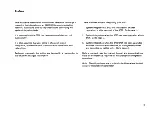
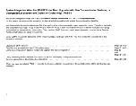
Page 4: ...sion bar to the left of the changed information There are three ways of integrating your 3720 1 System integration at 3720 first installation or after relocation or after removal of the 3721 Go to pag...

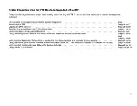
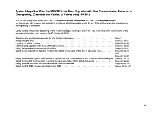
Page 5: ...tion data file COF function to define the speeds of the direct attached lines Using the line description file function to update the lin e characteristics and compute the line weights Using the link I...

Page 6: ...t function Using the configuration data file function to define the speeds of the direct attached lines Using the line description file functions to update the line characteristics and compute the lin...

Page 7: ...etup Instructions for the remaining setup tasks Then perform PASS 2 on next page when requested to do so in the Feature Addition Instructions or Setup Instructions Carry out the integration according...

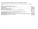
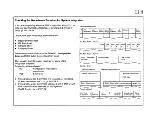
Page 8: ...ecking the worksheets required for the System Integration Initializing the 3720 Logging on at the console Familiarizing yourself with the 3720 function menu Using the password management function Usin...

Page 9: ......

Page 10: ...e sheets NO Contact your installation coordinator YES See below If integrating when the 3720 is first installed or relocated or after removal of the 3721 go to STEP 2 If integrating when the 3720 is u...

Page 11: ...tion of the setup 2 The console s and or the modem s or data circuit terminating equipment OCEs to be a ttached have been placed on the site and prepared for attachment according to their documentatio...

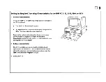
Page 12: ...ort cable part number 7837400 which adapts the 3720 local console to the PC COM1 port IBM PC remote console connection For remote console operation a modem attachment cable such as the IBM PC communic...

Page 13: ...or attaching the console later 3 Go to STEP 5 CONSOLE SHEET 37 Model 0 PU Name Serial Number 0 Order Number Operator Console Remote Support Facility Console Description Modem Description 3720 side Cab...

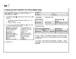
Page 14: ...in doubt An IBM 3101 Model 23 Any other equipment that is equivalent to the IBM 3101 Model 2x 2 Check that your local or remote console 0 is the one specified on your Console Sheet If not contact your...

Page 15: ...a long stop that will handle low quality transmissions 2 Does your console have these characteristics YES If attaching NO A local console go to STEP 15 A remote console go to STEP 13 An RSF link go t...

Page 16: ...tics for the IBM 3161 3163 or 3164 1 Select the required characteristics by using the setup menu and the select menu refer to the description of setup menu values in IBM 316113163 ASCII Display Statio...

Page 17: ...e an RSF link go to STEP 14 Sample Setup Menu HACHINE HODE L _ i OPERATING MODE J HAIN PORT f I PARITY L TURNAROlN CHARACTER L _______ 1 STOP BIT L j WORD LENGTH BITS i 7 1 RESPONSE DELAY HS i ioo i B...

Page 18: ...as COM1 primary asynchronous adapter Refer to the option instructions for the asynchronous communication adapter in the IBM PC Guide to Operations manual for information on the installation and config...

Page 19: ...Carriage Return Y CR N CR LF Y Y Null Suppress Y Yes N No Y Y Character Sent at End of Message l ETX 2 CR 3 EOT 4 XOFF 2 4 Scrolling Y Yes N No Y N 2 If attaching A local console but you do not have...

Page 20: ...you have an IBM 3101 you must select the required operating characteristics For more detailed information refer to the IBM 3101 Display Terminal Description GA18 2033 2 Locate the switches in the IBM...

Page 21: ...f you use the IBM 3101 as a remote console as shown in G 3 If attaching A local console but you do not have an RSF link go to STEP 15 A remote console go to STEP 13 A local console and you also have a...

Page 22: ...ite Connection over a switched line Duplex operation Asynchronous transmission Manual dialing Transmission speed V 22B 1200 bps Transmission speed V 22bis 1200 bps 3 If you also have an RSF link go to...

Page 23: ...plex transmission Synchronous transmission Synchronous tram mission Auto answer feature Auto answer feature Transmission speed Transmission speE d 1200 bps 1200 bps Clocking modem clock Clocking DTE 3...

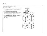
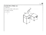
Page 24: ...D 15 Opening the 3720 or 3721 Rear Doors 1 Insert the key 2 Turn the key clockwise to open the rear door 3 Put the key in a safe place 4 Go to STEP 16...

Page 25: ...16 D Locating the 3720 Sockets for Console Connection 1 Find the three console sockets Ensure that all three sockets are empty If not empty remove any wrap blocks that are installed 2 Go to STEP 17...

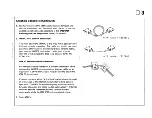
Page 26: ...it to the above console cable This short cable will adapt the console cable to the PC COM1 port 3 Push the 3720 end of the console cable firmly into the 3720 socket labeled DIRECT ATT 4 Attach the oth...

Page 27: ...o the modem using the modem documentation 5 Position the modem switches to the positions shown on the Console Sheet 6 Connect the modem to the telephone line At the remote console site 1 Find the mode...

Page 28: ...he 3720 plug firmly into the 3720 socket labeled RSF 4 Attach the other end of the cable to the modem using the modem documentation 5 Position the modem switches to the positions shown on the Console...

Page 29: ...o your 3720 must be held in place by means of a clamp Three clamps and three accompanying wingnuts were delivered with the 3720 and kept by your installation coordinator 1 Get the required number of c...

Page 30: ...e clamp positions on your 3720 2 Place the clamp around the cable i 3 Line up the clamp with the threaded stud on the frame 4 Put the wingnut onto the threaded stud and turn until secure 5 Repeat unti...

Page 31: ...ockwise to loosen a nd remove the cable retainer in the sequence shown in the upper illustration 3 Line up the console cables within the cable retainer area 4 Replace the cable retainer in position in...

Page 32: ...D 23 Closing the Rear Door 1 Turn the key counterclockwise to lock the rear door 2 Go to STEP 24...

Page 33: ...24 D Opening the Front Door 1 Get the key 2 Turn the key counterclockwise to open the front door 3 If your 3720 is a Model 1 or 11 go to STEP 25 If your 3720 is a Model 2 or 12 go to STEP 27 0 0...

Page 34: ...for more than two minutes a Set the power switch to Power Off b Restart from 1 If FEF is still not displayed or any power problem occurs refer to the 3720 3721 Problem Determination Guide or contact t...

Page 35: ...te console go to STEP 29 Note For more detailed information refer to the 3720 3721 Operator s Guide POIIER ON DPOWER OFF FUNCTION SELECT GENERAL NE FUNCTION RESET REQUEST START DOD CHANNEL ADAPTER INT...

Page 36: ...d for more than two minutes a Set the power switch to Power Off b Restart from 1 If FEF is still not displayed after three attempts or if any power problem occurs refer to the 372013721 Problem Determ...

Page 37: ...onsole switch to Console 4 Power on the console The copyright screen is displayed If not go to the IBM 3720 3721 Communication Control ers Problem Determination Guide GA33 0086 5 To access the next sc...

Page 38: ...in operation To connect through to the 3720 Dial the telephone number of the 3720 site Wait until you hear the answer tone Set the modem at the console site to data mode Hang up 4 The copyright screen...

Page 39: ...current password then go to STEP 31 In all other cases such as installation or relocation you use the default password IBM3720 Enter IBM3 720 Press Note You can change this to your own password later...

Page 40: ...mon to all functional screens It displays Operator control messages Function messages to inform you of the progress of the function or to indicate errors 4 Go to STEP 32 D 31 Machine Status Area CUSTO...

Page 41: ...3 Machine Status Area CUSTOMER 10 3720 1 FUNCTION ON SCREEN SYSTEM INPUT AREA SJA T TERMINATE OFF LOGOFF PF1 HOVE TO SIA CONFIG DATA FILE CDF CONTROL PRGH PROC C DISK FUNCTIONS OF DISK IPL INFO 011 EV...

Page 42: ...TEP 34 Machine Status Area CUSTOHER ID 3720 1 FUNCTION ON SCREEN SYSTEH INPUT AREA ISlA T TERMINATE OFF LOGOFF PF1 HOVE TO SIA CONFIG DATA FILE COF LINE DESCR FILE LDF CONTROL PRGM PROC C LINE INTERF...

Page 43: ...hey allow access by authorized persons only Note Make sure you can remember the passwords at any time by writing them down and keeping them confidential If you forget a password refer to the password...

Page 44: ...LE CDF LINE DESCR FILE LDF CONTROL PRCM PROC C LINE INTERF DPLY LID DISK FUNCTIONS OF LINE THRESHOLD LTH DISK IPL INFO OIl LINK IPL PORTS LKP EVENT LOG DISPLAY E LINK TEST LT IHL MOSS IHL LOAD LK TEST...

Page 45: ...onfigurating the 3720 for the first time enter the default password IBM3720 Then press 3 Go to STEP 37 Machine Status Area CUSTOMER 10 3720 1 SERIAL NUMBER FUNCTION ON SCREEN PASSWORDS SYSTEM INPUT AR...

Page 46: ...INPUT AREA SIA T TERMINATE OFF LOGOFF PFl HOVE TO SIA PF2 CCU FNCTN PF3 ALARM SELECT OPTION 1 UPDATE MANAGEMENT PASSWORD 2 UPDATE LOCAL PASSWORD 3 UPDATE REHOTE CUSTOMER PASSWORD 4 UPDATE REHOTE MAINT...

Page 47: ...etic Press The following message is displayed PASSWORD HAS BEEN UPDATED L _ _ __ 3 To return to the previous menu press SEND EJ 4 If you have A local console go to STEP 39 A remote console go to STEP...

Page 48: ...AREA SIA T TERMINATE OFF LOGOFF PF1 MOVE TO SIA PF2 CCU FNCTN PF3 ALARM SELECT OPTION 1 UPDATE MANAGEMENT PASSWORD 2 UPDATE LOCAL PASSWORD 3 UPDATE REMOTE CUSTOMER PASSWORD 4 UPDATE REMOTE MAINTENANC...

Page 49: ...t be alphabetic Press The following message is displayed PASSWORD HAS BEEN UPDATED 3 To return to the previous menu press 4 If you have A remote console go to STEP 41 A local console go to STEP 48 Mac...

Page 50: ...INPUT AREA SIA T TERMINATE OFF LOGOFF PFl HOVE TO SIA PF2 CCU FNCTN PF3 ALARM SELECT OPTION 1 UPDATE MANAGEMENT PASSWORD 2 UPDATE LOCAL PASSWORD 3 UPDATE REMOTE CUSTOMER PASSWORD 4 UPDATE REMOTE MAIN...

Page 51: ...he remote customer password mu t bEl different from the remote maintenance password The following message is displayed REMOTE PASSWORD HAS BEEN UPDA ED 3 To return to the previous menu press EJ 4 Go t...

Page 52: ...rd 3 Go to STEP 44 Machine Status Area CUSTOMER 10 3720 1 SERIAL NUMBER FUNCTION ON SCREEN PASSWORDS SYSTEM INPUT AREA SIA T TERMINATE OFF LOGOFF PF1 MOVE TO SIA PF2 CCU FNCTN PF3 ALARM SELECT OPTION...

Page 53: ...id only in the US Then press I SEN The following message is displayed PASSWORD AND RSF MODEM TRANSMISSION MODE HAVE BEEN UPDATED 4 To return to the previous menu press 5 Once you have updated the remo...

Page 54: ...ce password and its temporary or permanent status when you next need a maintenance call To select temporary access go to STEP 46 To select permanent access go to STEP 47 Machine Status Area CUSTOMER 1...

Page 55: ...8 Machine Status Area CUSTOMER ID 3720 1 SERIAL NUMBER FUNCTION ON SCREEN PASSWORDS SYSTEM INPUT AREA SIA T TERMINATE OFF LOGOFF PF1 MOVE TO SIA PF2 CCU FNCTN PF3 ALARM SELECT OPTION 1 UPDATE MANAGEME...

Page 56: ...R 10 3720 1 SERIAL NUMBER FUNCTION ON SCREEN PASSWORDS SYSTEM INPUT AREA SIA T TERMINATE OFF LOGOFF PF1 HOVE TO SIA PF2 CCU FNCTN PF3 ALARM SELECT OPTION 1 UPDATE MANAGEMENT PASSWORD 2 UPDATE LOCAL PA...

Page 57: ...A T TERMINATE OFF LOGOFF PF1 HOVE TO SIA PF2 CCU FNCTN PF3 ALARM SELECT OPTION 1 UPDATE MANAGEMENT PASSWORD 2 UPDATE LOCAL PASSWORD 3 UPDATE REMOTE CUSTOMER PASSWORD 4 UPDATE REMOTE MAINTENANCE PASSWO...

Page 58: ...he 3720 is being installed for the first time or relocated and you want to change the customer identification for this controller go to STEP 50 5 In all other cases go to STEP 52 D 49 Machine Status A...

Page 59: ...STEM INPUT AREA SIAl T TERMINATE OFF LOGOFF PFl MOVE TO SIA PF2 CCU FNCTN PF3 ALARM SELECT OPTION 1 UPDATE MANAGEMENT PASSWORD 2 UPDATE LOCAL PASSWORD 3 UPDATE REMOTE CUSTOMER PASSWORD 4 UPDATE REMOTE...

Page 60: ...ation a maximum of sixteen alphanumeric characters is allowed then press The following message is displayed CUSTOMER IDENTIFICATION HAS BEEN UPDATED 2 To return to the password option menu press EJ 3...

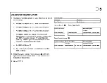
Page 61: ...are upgrading your 3720 with new communication features or downgrading PASS 1 only gl to STEP 54 Enter the speed bps of all direct attache j lines that use synchronous protocols for the first install...

Page 62: ...displayed in the upper part of Line Dest L1C Port Controller Cable Groupl Cable the screen Interface Type Pos Address Clocking Part Number Length If you have a 3721 check that you have the sheet for i...

Page 63: ...nly go to STEP 55 PASS 2 only go to STEP 57 Machine Status Area CUSTOMER 10 3720 1 FUNCTION ON SCREEN SYSTEM INPUT AREA SIA T TERMINATE OFF LOGOFF PF1 MOVE TO SIA eONFIG DATA FILE CDF CONTROL PRGM PRo...

Page 64: ...hine Status Area 2 To select the upgrade option press GJ sell CUSTOMER 10 3720 1 FUNCTION ON SCREEN CONFIG DATA FILE SERIAL NUMBER SYSTEM INPUT AREA SIA T TERMINATE OFF LOGOFF PFl MOVE TO SIA PF2 CCU...

Page 65: ...quest the person doing the setup to check that all new conlmunication features are correctly plugged Then return to STEP 55 4 If the above message is still notdisplayeci re fer to the 372013721 Proble...

Page 66: ...y option press 4 If you are upgrading your 3720 with new communication features or downgrading PASS 1 o nly go to STEP 63 5 Otherwise go to STEP 58 D 57 Machine Status Area CUSTOMER ID 3720 1 SERIAL N...

Page 67: ...frame The PLS option is alwa s at the bottom of the list 2 To select the PLS option you require entel its option number then press 3 Go to STEP 59 Machine Status Area CUSTOMER ID 3720 1 SERIAL NU 1BE...

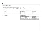
Page 68: ...e line address is in the Port Address column 2 Enter the line address of the first direct att ched line listed on your Plugging Sheet Press 3 If any message is displayed see STEP 108 otherwise go to S...

Page 69: ...peed or the default line spe43d 9600 bps 3 To select the Speed Update screen press 4 If any message is displayed see STEP 10a otherwise go to STEP 61 Machine Status Area CUSTOMER 10 3720 1 SERIAL NUMB...

Page 70: ...r IML is performed during the IPL later 3 If any message other than the one above is displayed see STEP 108 Otherwise go to STEP 62 Machine Status Area CUSTOMER 10 3720 1 SERIAL NUMBER FUNCTION ON SCR...

Page 71: ...see STEP 108 5 Once you have updated the speed of all direGt attached lines quit and return to the CDF option menu by pressing PF6 6 If you are upgrading your 3720 with new ommunication procedures or...

Page 72: ...pancy between your displayed configuration and the actual configuration The person in charge of the setup must check that the required communication features are correctly placed and plugged in your c...

Page 73: ...guration by pressing Then go to STEP 65 4 If you updated the configuration for a 3720 and 3721 select the whole configuration by pressin 8 ISEN Then go to STEP 65 Machine Status Area CUSTOMER 10 3720...

Page 74: ...the line addresses of the cables attached to the Lie cassettes in the basic or expansion frame 2 If you selected display option 1 the first screen displayed shows the basic frame configuration To disp...

Page 75: ...u is displayed 5 If you are upgrading with new communic3 tion features or downgrading PASS 1 only return to the Fea ture Addition Instructions or Setup Instructions to have the hardware checkout perfo...

Page 76: ...iption file LDF Use the LDF function to enter and display the configuration of your 3720 3721 1 For this function you need the Requirements and Plugging Sheets shown in STEP 68 These sheets list the l...

Page 77: ...ine address displayed by the LDF is the port address o shown on the Plugging Sheet Use the cross reference G next to the port address on the Plugging Sheet to find that line on the Requirements Sheet...

Page 78: ...USTOMER ID 3720 1 FUNCTION ON SCREEN SYSTEM INPUT AREA SIA T TERMINATE OFF LOGOFF PF1 MOVE TO SIA CONFIG DATA FILE CDF CONTROL PRGH PROC C DISK FUNCTIONS DF DISK IPL INFO 011 EVENT LOG DISPLAY E IML M...

Page 79: ...ed Consequently it cannot he d43scribed 2 To describe the lines in the NOT DESeRIB 0 status go to the update mode by pressing Starting from line 0 the first line installed is displayed 3 Go to STEP 71...

Page 80: ...of the lines used in the new configuration go to the update mode by pressing Starting from line 0 the first line installed is displayed 3 If the line you selected is a token ring attachment 3720 Model...

Page 81: ...isplayed was described in the previious screen its displayed characteristics corre 5pond to the previous configuration 4 If the characteristics on the sheet are diffe rent from those displayed you mus...

Page 82: ...configuration symbolic name 3 If you have now entered or updated the characteristics of all installed lines go to STEP 78 4 To update the next line press 5 If the next line is a token ring attachment...

Page 83: ...onfiguration 4 If the characteristics on the sheet are different from those displayed you must update the line chara teristics 5 Go to STEP 75 Machine Status Area CUSTOMER ID 3720 1 SERIAL NUMBER FUNC...

Page 84: ...D 75 Machine Status Area CUSTOMER ID 3720 1 SERIAL NUHBER FUNCTION ON SCREEN LINE DESCR FILE SYSTEM INPUT AREA SIA T TERMINATE OFF LOGOFF PF1 MOVE TO SIA PF2 CCU FNCTN LINE 2 NAHE NICE01 SCANNER 1 BA...

Page 85: ...ERIAL NUMBER FUNCTION ON SCREEN LINE oESCR FILE SYSTEM INPUT AREA SIA T TERMINATE OFF LOGOFF PFl MOVE TO SIA PF2 CCU FNCTN LINE 2 NAME NICEOI SCANNER 1 BASB PROTOCOL SOLe FOX SPEED NONE ENTER LINE NAM...

Page 86: ...Then return to STEP 72 D 77 Machine Status Area CUSTOMER ID 3720 1 SERIAL NUMBER FUNCTION ON SCREEN LINE OESCR FILE SYSTEM INPUT AREA SIA T TERMINATE OFF LOGOFF PF1 MOVE TO SIA PF2 CCU FNCTN LINE 2 N...

Page 87: ...Continue 5 To terminate the LDF function press Machine Status Area CUSTOMER ID 3720 12 SERIAL NUMBER FUNCTION ON SCREEN LINE DESCR FILE SYSTEM INPUT AREA CSIA T TERMINATE OFF LOGOFF ADDRESS NAME 0 PAR...

Page 88: ...communication controller can have its control program loaded via a channel attachment For all 3720 Models up to eight IPL ports can be defined but any defined IPL port must have a cable installed The...

Page 89: ...cility Duplex Half duplex Switched line Answer tone Ring indicated Direct attached or external clock Data rate Enable timer in O 1 second intervals If you are deleting a port enter space ins1ead of th...

Page 90: ...l program transferred via an SDLe link go to STEP 84 Machine Status Area CUSTOMER 10 3720 1 FUNCTION ON SCREEN SYSTEM INPUT AREA SIA T TERMINATE OFF LOGOFF PFl HOVE TO SIA CONFIG DATA FILE CDF CONTROL...

Page 91: ...options quit and terminate the LKP function by pressing In this way you terminate the link IPL port function without modifying the link port characteris ics Then repeat STEP 81 to access the LKP displ...

Page 92: ...your Requirements Sheet 2 Return to the LKP option screen by pressing 3 The LKP option screen is displayed 4 Go to STEP 84 Machine Status Area CUSTOMER ID 3720 1 SERIAL NUMBER FUNCTION ON SCREEN LINK...

Page 93: ...your IPL Port Sheet 3 Refer to your IPL Port Sheet and find the nlimbEH of the first installed IPL port To enter its characteristics or delete it ente r its port number then press 4 Go to STEP 85 Mac...

Page 94: ...ished Return to the LKP option screen Select the Link IPL port common options 6 Go to STEP 86 D 85 Machine Status Area CUSTOMER 10 3720 1 SERIAL NUH8ER FUNCTION ON SCREEN LINK IPL PORTS SYSTEM INPUT A...

Page 95: ...ated the cha actHristics of all common options terminate the LKP fun tion by pressing 5 The 3720 basic menu is displayed 6 If you do not have an RSF link or if you have upgraded your 3720 with new com...

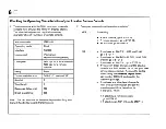
Page 96: ...serial number of the 3720 whose RSF link you want tested e The telephone number of the RSF modem f Whether the password is temporary or permanent 2 Go to STEP 88 Information required by the IBM Hardwa...

Page 97: ...ou wrote in the previous step 2 Switch the modem on 3 Telephone your IBM Hardware Central Ser ice you should get the telephone number from your installation coordinator Tell them That you want to be r...

Page 98: ...or 8 When you have updated the configuration of an upgraded or downgraded 3720 2 To perform this function insert the requited diskettes in the 3720 diskette drive when prompted on the screerL If you a...

Page 99: ...ervices GA33 0066 2 Find the required backup diskettes in the diskette holder inside the 3720 front door 3 Go to STEP 91 I J _ c J c c J c J c l E J E J c J c l c l E J c J E J E Jc 7E J E J E J E Jc...

Page 100: ...G DATA FILE CDF LINE DESCR FILE LDF CONTROL PRGM PROC C LINE INTERF DPLY LID DISK FUNCTIONS DF LINE THRESHOLD LTH DISK IPL INFO 011 LINK IPL PORTS LKP EVENT LOG DISPLAY E LINK TEST LT IML MOSS IML LOA...

Page 101: ...a CUSTOHER 10 3720 1 FUNCTION ON SCREEN DISK FUNCTIONS SYSTEM INPUT AREA SIA T TERMINATE OFF LOGOFF PF1 MOVE TO SIA DISK FUNCTION SELECTION SELECT ONE OF THE FOLLOWING FUNCTION 1 EC MICROCODE INSTALLA...

Page 102: ...3 If you have a 3720 only press 4 If you have a 3720 and a 3721 To have the same save identification applied to the 3721 press 5 Go to STEP 94 D 93 Machine Status Area CUSTOMER 10 3720 1 SERI AL NUHBE...

Page 103: ...nd the first diskette 3 Go to STEP 95 Machine Status Area CUSTOMER ID 3720 1 FUNCTION ON SCREEN DISK FUNCTIONS SYSTEM INPUT AREA SIA T TERMINATE OFF LOGOFF PF1 MOVE TO SIA SAVE DISK ONTO DISKETTES MOU...

Page 104: ...iskette drive 8 To save the contents of the disk press The following message is displayed SAVE DISK ONTO PRIMARY DISKETTE IN PROGRESS When the save is completed the following message is displayed DISK...

Page 105: ...yed Machine Status Area 2 Go to STEP 97 CUSTOMER ID 3720 1 SERIAL NUMBER FUNCTION ON SCREEN DISK FUNCTIONS SYSTEM INPUT AREA SIA T TERMINATE OFF LOGOFF PF1 MOVE TO SIA PF2 CCU FNCTN PF3 ALARM SAVE DIS...

Page 106: ...skette drive 7 To save the contents of the disk press The following message is displayed SAVE DISK ONTO EXPANSION DISKETTE IN PROGRESS When the save is completed the following message is displayed DIS...

Page 107: ...is displayed 2 Go to STEP 99 Machine Status Area CUSTOMER 10 3720 1 SERIAL NUMBER FUNCTION ON SCREEN DISK FUNCTIONS SYSTEM INPUT AREA 511 T TERMINATE OFF LOGOFF PF1 HOVE TO 511 PF2 CCU FNCTN PF3 ALARM...

Page 108: ...the contents of the disk press I SEN The following message is displayed SAVE DISK ONTO SECONDARY DISK TTE IN PROGRESS When the save is completed the following message is displayed DISK SAVE TO SECONDA...

Page 109: ...pted press 4 Terminate the disk function by pressing 5 The 3720 basic menu is displayed 6 Go to STEP 101 Machine Status Area CUSTOMER 10 3720 1 SERIAL NUMBER FUNCTION ON SCREEN DISK FUNCTIONS SYSTEM I...

Page 110: ...Storing the Backup DiskeHes 1 Replace all backup diskettes in their respective envelopes 2 Put all backup diskettes in the diskette holder inside the front door of the 3720 3 Go to STEP 102 D 101...

Page 111: ...nication controller During initialization the control program and the microcode are loaded 2 You can now IPL your communication contr lIer from either The operator panel refer to the 3720 37 1 Communi...

Page 112: ...opropriate position 2 In the 3720 basic menu select the IPL 3720 function by pressing 3 Go to STEP 104 Machine Status Area CUSTOMER 10 3720 1 FUNCTION ON SCREEN SYSTEM INPUT AREA SIA T TERMINATE OFF L...

Page 113: ...chine Status Area To confirm your selection press CUSTOMER 10 3720 1 SERIAL NUMBER FUNCTION ON SCREEN IPL SYSTEM INPUT AREA SIA 2 Go to STEP 105 T TERMINATE OFF LOGOFF PFl HOVE TO SIA PF2 CCU FNCTN PF...

Page 114: ...d where n is the number of the phase No operator action is required When phase 4 is finished the following message is displayed IPL PHASE 1 PHASE 2 PHASE 3 PHASE 4 ENABLED PORTS CA NN L NNNNNNNN 2 If...

Page 115: ...3 PHASE 4 IPL COMPLETED If you are using the panel X 000 appears on the display when IPL has completed without errors If you IPL from diskette X FFD means IPL completed without errors 3 When this is...

Page 116: ...D 107 Close the 3720 and or 3721 Front Doors 1 Get the key 2 Close the front door 3 Turn the key clockwise to lock 4 Give the key to your installation coordinator 5 END OF SYSTEM INTEGRATION t J...

Page 117: ...nd CABLE NOT INSTALLED on your R4 quirements Sheet may be re enter CABLE NOT IN DIRECT ATTACHMENT wrong Check with the person in charge of the configuration INCORRECT PASSWORD You enten3d an incorrect...

Page 118: ...d for the next edition of this manual Thank you for taking the time and trouble to fill out this form If you would like a reply please give details overleaf No postage stamp necessary if mailed in the...

Page 119: ...WILL BE PAID BY ADDRESSEE International Business Machines Corporation Department 6R1 LG 180 Kost Road Mechanicsburg PA 17055 Please Do Not Staple Fold and tape NO POSTAGE NECESSARY IF MAILED IN THE UN...

Page 120: ...be considered for the next edition of this manual Thank you for taking the time and trouble to fill out this form If you would like a reply please give details overleaf No postage stamp necessary if m...

Page 121: ...ILL BE PAID BY ADDRESSEE International Business Machines Corporation Department 6R1 LG 180 Kost Road Mechanicsburg PA 17055 Please Do Not Staple Fold and tape NO POSTAGE NECESSARY IF MAILED IN THE UNI...

Page 122: ..._ GA33 0067 3 GA33 0067 03 Printed in USA...

Reviews: