Chapter 1. Technical description
15
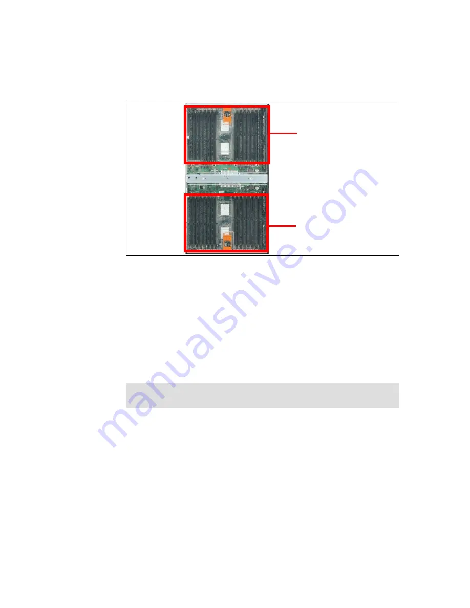
Figure 1-8 Memory-board assembly, showing the two memory ports
The memory-board assembly contains 28 DIMM slots. All DIMM slots can be
used when 512 MB or 1 GB DIMMs are used. If 2 GB DIMMs are used, up to 20
DIMMs slots can be used. The maximum installable memory is 40 GB (using 2
GB DIMMs).
The memory-board assembly is also equipped with LEDs for light path
diagnostics for each DIMM. In addition, the assembly is equipped with LEDs for
the following:
Power to memory port 1
Power to memory port 2
Hot-plug memory enabled
For information about installing memory in the memory-board assembly, see
3.1.2, “Memory” on page 41.
1.5.2 Processor-board assembly
The x450 processor-board assembly is located under the memory-board
assembly, as shown in Figure 1-7 on page 14. It is installed from the top of the
server and mounts to the side of the midplane using two levers on the side, as
shown in Figure 1-9 on page 16.
Restriction:
The ability to hot-add or hot-replace memory is not available in
the x450.
There are 14 DIMM slots in each
of the two ports, for a total of 28
DIMMs.
Memory Port 1
Memory Port 2
Summary of Contents for 450 xSeries
Page 2: ......
Page 8: ...vi IBM xSeries 450 Planning and Installation Guide ...
Page 80: ...66 IBM xSeries 450 Planning and Installation Guide ...
Page 130: ...116 IBM xSeries 450 Planning and Installation Guide ...
Page 148: ...134 IBM xSeries 450 Planning and Installation Guide ...
Page 156: ...142 IBM xSeries 450 Planning and Installation Guide ...
Page 157: ... 0 2 spine 0 17 0 473 90 249 pages IBM xSeries 450 Planning and Installation Guide ...
Page 158: ......
Page 159: ......


