1.
Connect
the
cables
as
shown
in
as
shown
in
“Rear
view
and
connectors”
on
page
5.
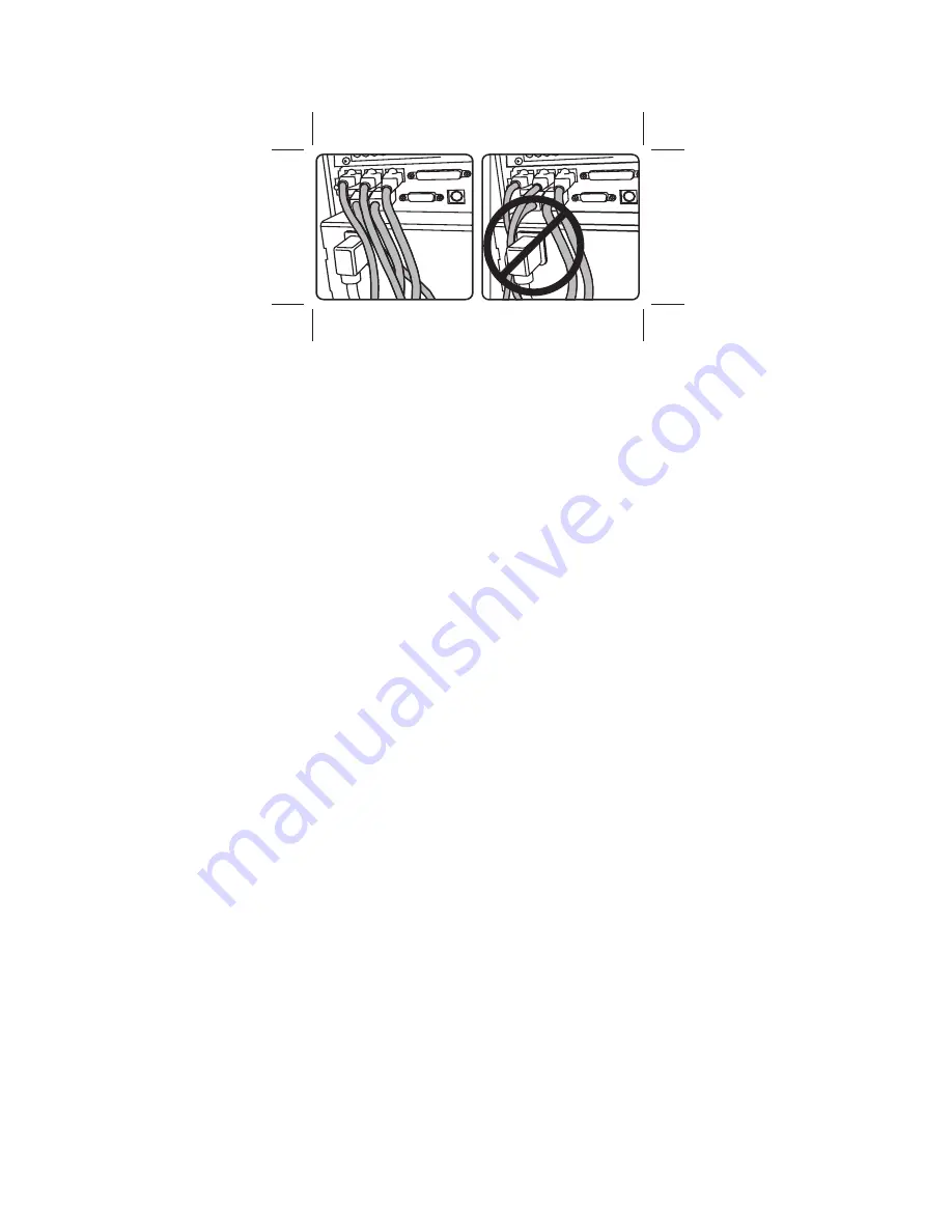
Signal
cables
must
be
routed
to
the
right
of
the
AC
power
cable,
as
shown
in
Figure
11.
2.
Secure
the
cables
to
the
cable-tie
bar
with
tie-warps
if
desired.
Cut
the
end
of
the
tie-wraps
flush
so
that
no
jagged
edges
are
exposed.
Attention:
The
rear
cover
will
not
close
properly
if
signal
cables
are
routed
to
the
left
of
the
AC
power
cable.
See
Figure
11
for
routing.
3.
For
cables
routed
under
the
counter,
install
a
cable
tie
around
all
rear
connector
panel
cables
exiting
through
the
hole.
Allow
sufficient
length
for
cleaning
and
servicing.
Figure
11.
Cable
routing
label
Installing
the
IBM
SurePOS
500
Model
514
Updated
October,
2008
Chapter
2.
Installing
the
IBM
SurePOS
500
Model
514
13
Summary of Contents for 4851 514
Page 2: ......
Page 8: ...Updated October 2008 vi SurePOS 500 Model 514...
Page 12: ...Updated October 2008 x SurePOS 500 Model 514...
Page 16: ...Updated October 2008 xiv SurePOS 500 Model 514...
Page 20: ...Figure 2 Serial number location Updated October 2008 4 SurePOS 500 Model 514...
Page 32: ...Installing the IBM SurePOS 500 Model 514 Updated October 2008 16 SurePOS 500 Model 514...
Page 64: ...Installing additional peripheral devices Updated October 2008 48 SurePOS 500 Model 514...
Page 68: ...Updated October 2008 52 SurePOS 500 Model 514...
Page 102: ...Updated October 2008 86 SurePOS 500 Model 514...
Page 138: ...Updated October 2008 122 SurePOS 500 Model 514...
Page 143: ...IBM IBM GA27 4004 GA27 4004 Updated October 2008 Appendix D Safety information 127...
Page 152: ...Updated October 2008 136 SurePOS 500 Model 514...
Page 156: ...Updated October 2008 140 SurePOS 500 Model 514...
Page 158: ...Updated October 2008 142 SurePOS 500 Model 514...
Page 161: ......
Page 162: ...Updated October 2008 GA27 4361 01...


