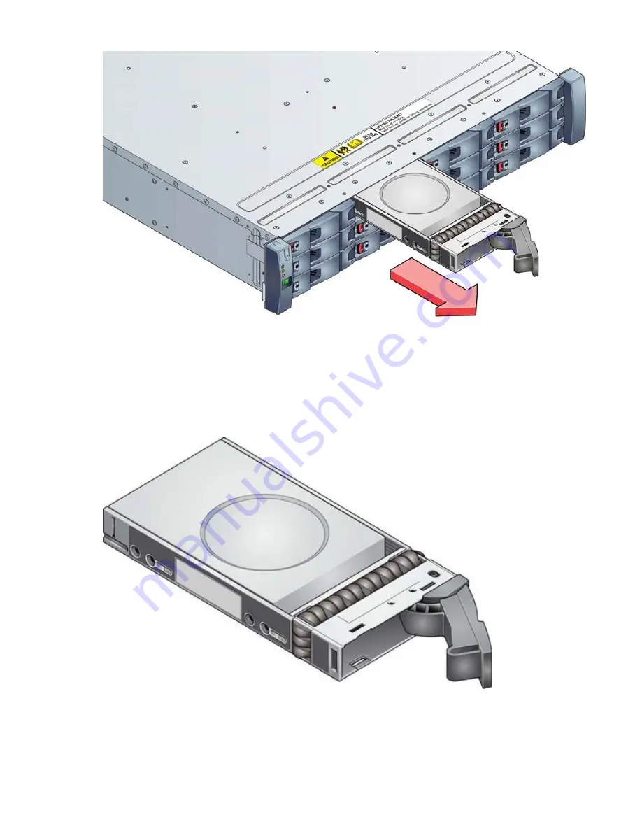
Figure 26. Removing a Drive Carrier Module (2 of 2)
4. Remove the module fully from the drive bay.
Installing a 3.5-inch Drive Carrier Module
Important: A drive carrier module cannot be installed if its anti-tamper lock is activated outside the
enclosure. Refer to the above section for the de-activation procedure.
1. Release the drive carrier handle, by depressing the latch in the handle as shown in the following figure.
Figure 27. Installing a Drive Carrier Module (1 of 2)
2. Put the drive carrier module into the enclosure as shown in the following figure. Make sure that the
drive carrier is in a position so that the drive points up and the handle opens from the left.
38 IBM Cloud Object Storage System: IBM Small J10 Disk Enclosure Manual
Summary of Contents for 4957-J10
Page 8: ...viii...
Page 10: ...x IBM Cloud Object Storage System IBM Small J10 Disk Enclosure Manual...
Page 15: ...European Community and Morocco Notice Germany Notice Safety and environmental notices xv...
Page 20: ...xx IBM Cloud Object Storage System IBM Small J10 Disk Enclosure Manual...
Page 33: ...Figure 13 Anti tamper Lock 3 5 Drive Chapter 2 System overview 13...
Page 34: ...14 IBM Cloud Object Storage System IBM Small J10 Disk Enclosure Manual...
Page 40: ...20 IBM Cloud Object Storage System IBM Small J10 Disk Enclosure Manual...
Page 44: ...24 IBM Cloud Object Storage System IBM Small J10 Disk Enclosure Manual...
Page 52: ...32 IBM Cloud Object Storage System IBM Small J10 Disk Enclosure Manual...
Page 68: ...48 IBM Cloud Object Storage System IBM Small J10 Disk Enclosure Manual...
Page 69: ......
Page 70: ...IBM...


