screw-thread support flange holes, ensure that the rails and fittings match the support flange
holes that are used on your rack. Do not install mismatched hardware by using washers or spacers.
If you do not have the correct rails and fittings for your rack, contact your IBM reseller.
Note: The system requires 2 EIA rack units (2U) of space.
Procedure
1. If you are installing the system into a rack that has round holes, you must install hardware onto the
rails. The four hole adapters in the rail kit allow the rails to be attached to racks with round holes on
the flanges. To install the hole adapters, complete the following tasks:
a. Attach the adapters to the rails. The adapters slide and snap into place on the rail.
Note: Each adapter is marked with either an A or a B. For the left rail, the A bracket should be in
front, and the B bracket should be in back. For the right rail, the B bracket should be in front, and
the A bracket should be in back.
b. Remove the screw from each adapter.
c. Continue with step “5” on page 7.
2. Select the appropriate EIA location unit number for the rails. Each EIA location contains three holes
for mounting hardware.
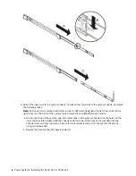
3. Each rail has two parts. Before you install the rails into the rack, you must separate them. To separate
the rails, extend the inner rail (A) and press the locking tab on the inner rail (B). Separate the inner
rail from the outer rail (C). Complete this task for each rail.
Installing and configuring your system and system features 5
Summary of Contents for 5104-22C
Page 1: ...Power Systems Installing the 5104 22C or 9006 22C IBM...
Page 4: ...iv...
Page 14: ...xiv Power Systems Installing the 5104 22C or 9006 22C...
Page 24: ...10 Power Systems Installing the 5104 22C or 9006 22C...
Page 35: ......
Page 36: ...IBM...


