background image

17.

Install the disk drives making sure that each disk drive is inserted back into the same slot from
which it was removed. For instructions, see “Removing and installing a disk drive” on page 3.

18.

Restore power to the power supplies of the disk drive enclosure and power on the system or
partition.

19.

Check the LEDs to make sure that the enclosure is fully operational.

Removing and installing a power supply

You can remove and install a power supply concurrently or nonconcurrently.

Attention:

Failure to follow the steps sequentially for this field replaceable unit (FRU) removal or

installation might result in damage to the FRU or system.

Use the following precautions whenever you handle electronic components or cables:

v

Attach a wrist strap to an unpainted metal surface of your hardware to prevent electrostatic discharge
(ESD) from damaging your hardware.

v

If you do not have a wrist strap, before removing the product from ESD packaging and installing or
replacing hardware, touch an unpainted metal surface of the system for a minimum of 5 seconds.

v

Keep all electronic components in the shipping container or envelope until you are ready to install
them.

v

If you remove and reinstall an electronic component, temporarily place the component on an ESD pad
or blanket, if available.

To remove and install a power supply, complete the following steps:

1.

Determine whether the repair can continue concurrently. To continue the repair concurrently, the
following conditions must be true:

v

A second power supply must already be installed.

v

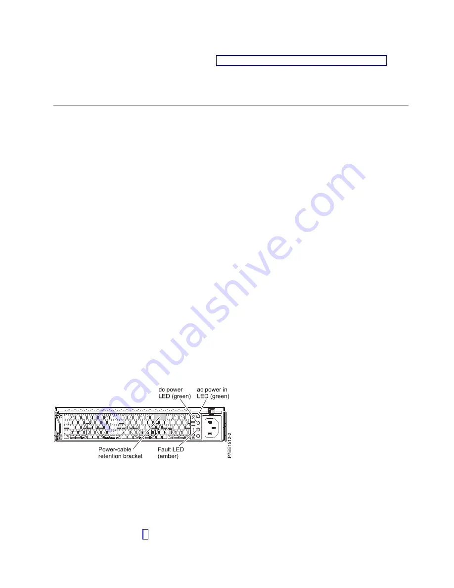
The second power supply LEDs must be set as follows:
– The dc power LED (green) is on solid.
– The fault LED (amber) is off.
– The ac power LED (green) is on solid.

Note:

If you decide to remove and replace the failing power supply with the power on, the

procedure must be performed in less than 15 minutes to prevent overheating.

2.

If any of these conditions are not true, continue the repair only after powering off the unit containing
the FRU that is being repaired, and begin with The power supply will be serviced nonconcurrently.
Otherwise, continue with The power supply will be serviced concurrently.

v

The power supply will be serviced concurrently

.

Do not remove power from the working power supply during this procedure. Remove the
power-cable retention bracket. Label and remove the power cable from the power supply to be
removed. Go to step 3.

Figure 8. Rear view of power supply

Removal and replacement procedures

9

Summary of Contents for 5887

Page 1: ...Power Systems 5887 removal and replacement procedures IBM...

Page 2: ......

Page 3: ...Power Systems 5887 removal and replacement procedures IBM...

Page 4: ...Notices manual G229 9054 and the IBM Environmental Notices and User Guide Z125 5823 This edition applies to IBM Power Systems servers that contain the POWER7 processor and to all associated models Cop...

Page 5: ...drive 3 Removing and installing an enclosure services manager 4 Removing and installing a midplane 5 Removing and installing a power supply 9 Notices 11 Trademarks 12 Electronic emission notices 12 C...

Page 6: ...iv...

Page 7: ...ct The documentation contains the safety information in your national language with references to the U S English source Before using a U S English publication to install operate or service this produ...

Page 8: ...ate v Connect any equipment that will be attached to this product to properly wired outlets v When possible use one hand only to connect or disconnect signal cables v Never turn on any equipment when...

Page 9: ...e customer to ensure that the outlet is correctly wired and grounded to prevent an electrical shock CAUTION v Do not install a unit in a rack where the internal rack ambient temperatures will exceed t...

Page 10: ...he route that you choose can support the weight of the loaded rack cabinet Refer to the documentation that comes with your rack cabinet for the weight of a loaded rack cabinet v Verify that all door o...

Page 11: ...This product might contain one or more of the following devices CD ROM drive DVD ROM drive DVD RAM drive or laser module which are Class 1 laser products Note the following information v Do not remove...

Page 12: ...hen you call C003 Power and cabling information for NEBS Network Equipment Building System GR 1089 CORE The following comments apply to the IBM servers that have been designated as conforming to NEBS...

Page 13: ...iew the installation or replacement procedure for the feature or part 3 Note the significance of color on your system Blue or terra cotta on a part of the hardware indicates a touch point where you ca...

Page 14: ...ystems networks and modems before you open the device covers unless instructed otherwise in the installation and configuration procedures v Connect and disconnect cables as described in the following...

Page 15: ...stall them v If you remove and reinstall an electronic component temporarily place the component on an ESD pad or blanket if available To remove a disk drive from the disk drive enclosure complete the...

Page 16: ...replacing hardware touch an unpainted metal surface of the system for a minimum of 5 seconds v Keep all electronic components in the shipping container or envelope until you are ready to install them...

Page 17: ...the open position b Gently slide the ESM into the enclosure until the ESM stops c Push the release levers to the closed position d Reconnect the SAS cable or cables to the ESM using the location info...

Page 18: ...ve each disk drive and label it with the slot from which it was removed See Removing and installing a disk drive on page 3 After the midplane is replaced the disk drives must be inserted back into the...

Page 19: ...e midplane assembly out of the enclosure 9 Remove the midplane a Remove the six screws that attach the midplane to the midplane assembly b Lift off the failed midplane Figure 4 Removing the midplane a...

Page 20: ...crews that you removed earlier in step 7d b Insert the four beveled screws that secure the midplane assembly to the front of the enclosure by using the four screws that you removed earlier in step 7c...

Page 21: ...pe until you are ready to install them v If you remove and reinstall an electronic component temporarily place the component on an ESD pad or blanket if available To remove and install a power supply...

Page 22: ...b Using the handle gently slide the power supply out of the enclosure supporting the bottom 4 Install the power supply a Hold the replacement power supply so that the handle is fully extended downwar...

Page 23: ...or changes in the product s and or the program s described in this publication at any time without notice Any references in this information to websites not owned by the manufacturer are provided for...

Page 24: ...acturer s support websites for updated information and fixes applicable to the system and related software Homologation statement This product may not be certified in your country for connection by an...

Page 25: ...tion requirements of EU Council Directive 2004 108 EC on the approximation of the laws of the Member States relating to electromagnetic compatibility IBM cannot accept responsibility for any failure t...

Page 26: ...Interference EMI Statement People s Republic of China Declaration This is a Class A product In a domestic environment this product may cause radio interference in which case the user may need to perfo...

Page 27: ...Erweiterungskomponenten von Fremdherstellern ohne Empfehlung von IBM gesteckt eingebaut werden EN 55022 Klasse A Ger te m ssen mit folgendem Warnhinweis versehen werden Warnung Dieses ist eine Einrich...

Page 28: ...vide reasonable protection against harmful interference in a residential installation This equipment generates uses and can radiate radio frequency energy and if not installed and used in accordance w...

Page 29: ...of EU Council Directive 2004 108 EC on the approximation of the laws of the Member States relating to electromagnetic compatibility IBM cannot accept responsibility for any failure to satisfy the pro...

Page 30: ...len sind die Ger te wie in den Handb chern beschrieben zu installieren und zu betreiben Des Weiteren d rfen auch nur von der IBM empfohlene Kabel angeschlossen werden IBM bernimmt keine Verantwortung...

Page 31: ...cial Use You may reproduce distribute and display these publications solely within your enterprise provided that all proprietary notices are preserved You may not make derivative works of these public...

Page 32: ...20...

Page 33: ......

Page 34: ...IBM Printed in USA...

Reviews: