Procedure
1. Remove the loop straps from the upper and lower CMA assemblies. The straps are used only for
shipping.
Installing the upper CMA assembly
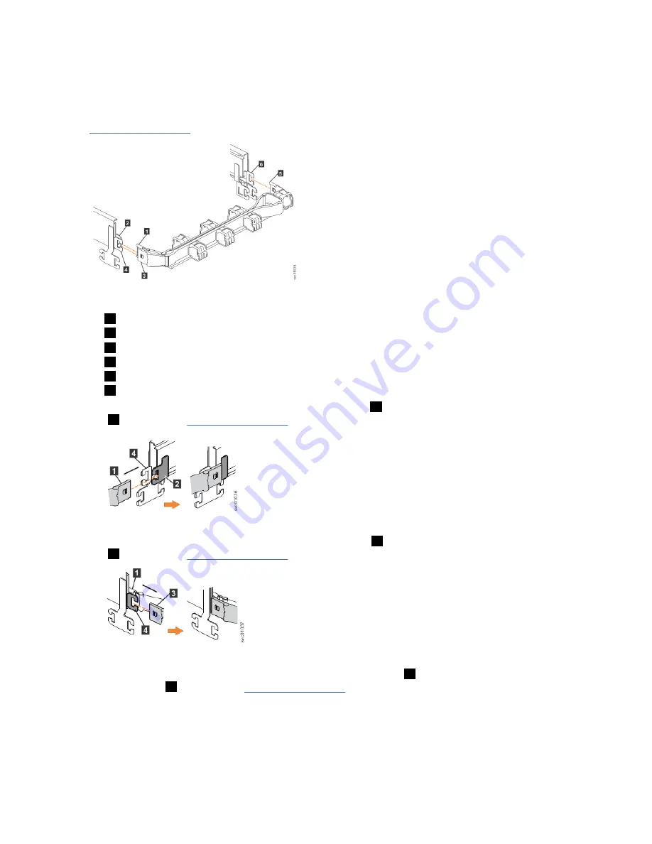
Figure 31 on page 38 shows the connectors on the upper CMA assembly.
Figure 31. Connectors for the cable management arm
1
Inner connector on upper CMA
2
Connector base on inner rail member
3
Outer connector on upper CMA
4
Connector base on outer rail member
5
Support rail connector on upper CMA
6
Connector base on outer rail member
2. Install the inner connector of the upper CMA assembly (
1
) to the inner member of the left support rail
(
2
), as shown in Figure 32 on page 38.
Figure 32. Install the inner connector of the upper CMA to the inner member of the support rail
3. Install the outer connector of the upper CMA assembly (
3
) to the outer member of the left support rail
(
4
), as shown in Figure 33 on page 38.
Figure 33. Install the outer connector of the upper CMA to the outer member of the support rail
4. Attach the support rail connector on the upper CMA assembly (
5
) to the connector base on the right
support rail (
6
), as shown in Figure 34 on page 39.
38 IBM Cloud Object Storage System
™
Version 3.15.6: J15 Appliance Manual
Summary of Contents for 5U92
Page 1: ...IBM Cloud Object Storage System Version 3 15 6 J15 Appliance Manual IBM...
Page 10: ...x...
Page 12: ...xii...
Page 24: ...xxiv IBM Cloud Object Storage System Version 3 15 6 J15 Appliance Manual...
Page 32: ...4 IBM Cloud Object Storage System Version 3 15 6 J15 Appliance Manual...
Page 140: ...112 IBM Cloud Object Storage System Version 3 15 6 J15 Appliance Manual...
Page 141: ......


