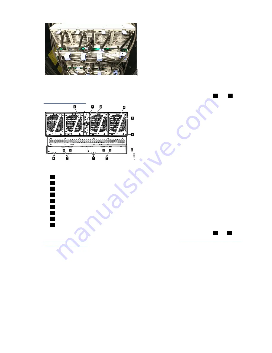
Figure 43. Power and SAS cable connections on the back of the enclosure
3. Verify that the disk enclosure and its components are operating as expected.
On the back of the disk enclosure, all four fans and the expansion canister indicators (
3
and
8
in
Figure 44 on page 44) become active when the power is connected.
Figure 44. Features on the rear of the 5U92 disk enclosure
1
Power cable connector for PSU 2
2
Power cable retention clamps
3
Fan module
4
Fan release latch
5
Fan fault indicator
6
Expansion canister
7
SAS ports and indicators
8
Expansion canister indicators
9
Power cable connector for PSU 1
On the front of the enclosure, the indicators on the front display panel and each PSU (
1
and
3
in
Figure 41 on page 43) are also lit when the power is connected. See “5U92 disk enclosure LEDs and
indicators” on page 45 for information about the status that is provided by the indicators.
4. Verify that the system recognizes the disk enclosure.
In the Manager GUI, view information about the system status and the disk enclosure.
• If the disk enclosure was powered off as part of a service procedure, view the information in the
Manager GUI to confirm that the enclosure is operating as expected.
Powering off the 5U92 disk enclosure
Before you power down a 5U92 disk enclosure, review the following procedure.
Before you begin
When you power off an disk enclosure, the drives in that enclosure are no longer available to the IBM
Cloud Object Storage System
™
.
44 IBM Cloud Object Storage System
™
Version 3.15.6: J15 Appliance Manual
Summary of Contents for 5U92
Page 1: ...IBM Cloud Object Storage System Version 3 15 6 J15 Appliance Manual IBM...
Page 10: ...x...
Page 12: ...xii...
Page 24: ...xxiv IBM Cloud Object Storage System Version 3 15 6 J15 Appliance Manual...
Page 32: ...4 IBM Cloud Object Storage System Version 3 15 6 J15 Appliance Manual...
Page 140: ...112 IBM Cloud Object Storage System Version 3 15 6 J15 Appliance Manual...
Page 141: ......


