IB
M
xS
er
ie
s
360
155
For the latest product & technical information, refer to the Information Sources on pages 2 and 3.
Updated 12/03/02
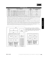
xSeries 360 contains five front-accessible drive bays located on the right side of the server. The top two bays contain the standard slim-line CD-ROM and 1.44MB
slim-line diskette drive. Three 3.5in slim-line, hot-swap drive bays are located beneath them. The IDE CD-ROM is docked to a media interposer card that is cabled to
the lightpath card before terminating at the system planar. The three SCA2-compliant hot-swap bays attach to a hot-swap backplane that connects to the integrated
single-channel Ultra160 controller through an integrated bus. For RAID configurations, a cable provided with the system is connected to one of the internal
connectors of the RAID controller and the other end of the cable is attached to a connector that supports the hot-swap HDD backplane, located on the planar
between slot one and the memory card, beneath the memory options.
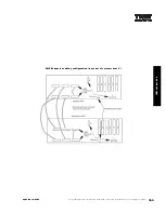
For additional information regarding internal cabling, refer to Appendix F: Internal Cabling Overview.
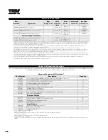
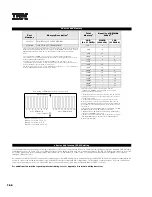
xSeries 360 Memory
Total Memory
1
Quantity of RDIMMs Added
2
1GB
(2x512MB
model)
2GB
(4x512MB
models)
256MB
(33L3281)
512MB
(33L3283)
1GB
(33L3285)
2GB
3GB
4
-
-
2.5GB
3.5GB
2
2
-
3GB
4GB
-
4
-
3.5GB
4.5GB
2
-
2
4GB
5GB
-
2
2
5GB
6GB
-
-
4
6GB
-
-
2
4
7GB
-
-
-
6
8GB (max)
3
8GB
3
-
-
8
This table does not represent all possible memory configurations.
1. Network operating systems may limit the maximum amount of addressable memory. See operating
system specifications for further information.
2. To obtain the quantity of memory identified in the “Total Memory” column, select the appropriate
row and order the quantity of RDIMMs identified in all columns for that row.
3. Requires removal of standard RDIMMs.
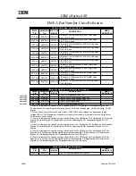
Part
Number
Memory Description
1
33L3281
256MB PC 1600 ECC DDR SDRAM RDIMM
33L3283
512MB PC1600 ECC DDR SDRAM RDIMM
33L3285
1GB PC1600 ECC DDR SDRAM RDIMM
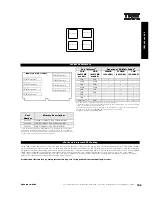
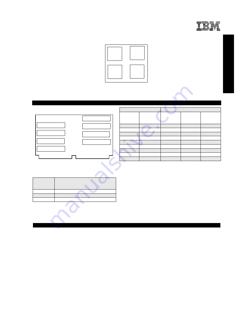
1. Due to two-way interleaving, all RDIMMs must be installed in pairs in the order
indicated by the diagram. Chipkill support is provided on the memory card. Only
installation in pairs is supported. The order of installation in pairs is sockets one and
two, three and four, five and six, and seven and eight.
xSeries 360 Internal SCSI Cabling
Processor 4
Processor 2
Processor 3
Processor 1
DIMM socket 5
DIMM socket 7
DIMM socket 3
DIMM socket 1
DIMM socket 6
DIMM socket 8
DIMM socket 4
DIMM socket 2
Memory Card Assembly


