background image


128

PC 300GL User Guide 


Summary of Contents for 628816U - PC 300 GL

Page 1: ...PC 300GL User Guide Types 6268 6278 and 6288...

Page 2: ......

Page 3: ...PC 300GL User Guide Types 6268 6278 and 6288 IBM...

Page 4: ...periodically made to the information herein these changes will be incorporated in new editions of the publication IBM may make improvements and or changes in the product s and or the program s describ...

Page 5: ...ish the installation 16 Arranging your workspace 16 Comfort 16 Glare and lighting 17 Air circulation 17 Electrical outlets and cable lengths 18 Chapter 3 Operating your computer 19 Starting your compu...

Page 6: ...n Setup Utility program 38 Changing keyboard speed 38 Setting the startup sequence 38 Setting remote administration 39 Interrupt and DMA resources 40 Power management features 40 Quick reference for n...

Page 7: ...uration Setup Utility program 85 Configuring startup devices 86 Chapter 7 Troubleshooting 87 Power on self test POST 88 Troubleshooting MAP 89 Diagnostic error codes and messages 92 POST errors 92 POS...

Page 8: ...ering publications 124 Appendix A Using the Software Selections CD 125 Features of the CD 125 Starting the CD 126 Using the Software Selections program 126 Appendix B Computer records 129 Serial numbe...

Page 9: ...les Remove all cables from devices Attach power cord to outlet First attach all cables to devices Electrical current from power telephone and communication cables is hazardous To avoid shock hazard co...

Page 10: ...caution when installing or modifying telephone lines Avoid using a telephone other than a cordless type during an electrical storm There may be a remote risk of electric shock from lightning Do not u...

Page 11: ...ssion IEC 825 and CENELEC EN 60 825 for Class 1 laser products When a CD ROM drive is installed note the following CAUTION Use of controls or adjustments or performance of procedures other than those...

Page 12: ...ble Dispose of the battery as required by local ordinances or regulations ATTENTION Danger d explosion en cas de remplacement incorrect de la batterie Remplacer uniquement par une batterie IBM de type...

Page 13: ...about the specific features of your computer To access this online publication see About Your Software The following publications contain more information about your computer Hardware Maintenance Manu...

Page 14: ...xii PC 300GL User Guide...

Page 15: ...machine type The model number machine type indicates the various features of the computer such as the type of microprocessor or the number of bays You can find this number on the small label on the f...

Page 16: ...by side The diskette drive is next to the power button and if your computer comes with a CD ROM drive it is next to the floppy drive When the desktop model is in its normal position drives horizontal...

Page 17: ...p of one another If your computer has a CD ROM drive it is installed in the bay at the top of the computer When the tower model is in its normal position the drives in the tower are horizontal with th...

Page 18: ...synchronous 168 pin dual inline DIMM unbuffered 100 MHz nonparity SDRAM 32 MB 64 MB 128 MB and 256 MB unbuffered DIMMs for a maximum of 512 MB DIMM heights up to 63 5 mm 2 5 inches 512 KB flash memor...

Page 19: ...M software Ability to store POST hardware test results Input output features 25 pin ECP EPP parallel port Two 9 pin 16550 UART serial ports Two 4 pin USB ports Mouse port Keyboard port 15 pin monitor...

Page 20: ...our Software for a detailed description of the preinstalled software Operating systems supported Microsoft Windows NT Workstation Versions 3 51 and 4 0 Microsoft Windows 95 and Windows 98 Operating sy...

Page 21: ...power management optional features in use Heat output Approximate heat output in British thermal units Btu per hour Minimum configuration 256 Btu hr 75 watts Maximum configuration 706 Btu hr 207 watt...

Page 22: ...nd the power management optional features in use Heat output Approximate heat output in British thermal units Btu per hour Minimum configuration 256 Btu hr 75 watts Maximum configuration 706 Btu hr 20...

Page 23: ...cable and power cord If you are missing an item contact your place of purchase Selecting a location for your computer Make sure you have an adequate number of properly grounded electrical outlets for...

Page 24: ...n the back of the desktop model computer You might not have all of the devices shown here Monitor USB 1 Parallel Microphone Headphone Line Out Line In Keyboard Mouse Serial 1 Serial 2 USB 2 1 2 Note T...

Page 25: ...e all of the devices shown here 1 2 USB Serial 2 Mouse Keyboard Serial 1 Printer Microphone Line In Line Out Headphone Monitor Note The connectors on the rear of the computer have color coded icons Ic...

Page 26: ...itor if it is not already attached then to the monitor connector and tighten the attachment screws Connect the keyboard cable to the gray keyboard connector Connect the mouse cable to the green mouse...

Page 27: ...er Any serial device or external modem in the serial connector Serial Device Desktop Serial Device Tower Any universal serial bus USB devices USB Device Desktop USB Tower Any optional devices such as...

Page 28: ...powers on for a few seconds then powers off This is normal operation In some circumstances the computer might not power off immediately when the power switch is pressed In this case hold the power sw...

Page 29: ...es for the monitor and the computer You see a logo screen while the computer performs a short self test When the task completes successfully the logo screen disappears the BIOS is loaded and the softw...

Page 30: ...and the kind of work you do Your comfort is of foremost importance but light sources air circulation and the location of electrical outlets also can affect the way you arrange your workspace Comfort...

Page 31: ...as the room lighting changes throughout the day Where it is impossible to avoid reflections or to adjust the lighting place an antiglare filter over the screen However these filters might affect the...

Page 32: ...nal placement of your computer When arranging your workspace Avoid the use of extension cords Whenever possible plug the computer power cord directly into an electrical outlet Keep power cords and cab...

Page 33: ...ate your computer with the cover off Starting your computer What you see and hear when you start up your computer depends on the settings in the Start Options menu of the Configuration Setup Utility p...

Page 34: ...T or accessing the Configuration Setup Utility program appear in the lower left corner of the screen Shutting down When you are ready to turn off your computer follow the shutdown procedure for your o...

Page 35: ...ng the diskette Inserting and removing diskettes To insert a 3 5 inch diskette hold the diskette with the label facing up and insert the end with the protective slide first Push the diskette into the...

Page 36: ...ator light on the front of the drive will activate to indicate that the drive is in use 4 To eject the CD press the Eject Load button When the tray slides out carefully remove the disk 5 Close the tra...

Page 37: ...ides notification of changes in the computer system even if the computer is powered off Working with DMI and Wake on LAN technologies Alert on LAN helps to manage and monitor the hardware and software...

Page 38: ...IBM PC LCCM is available for downloading at no additional charge Internet access fees excepted For more information or to download this software visit http www ibm com pc us desktop lccm System Migra...

Page 39: ...puter provided on the Software Selections CD that comes with your computer Video device drivers To take full advantage of the graphics adapter in your computer some operating systems and application p...

Page 40: ...mplies with the VESA Display Data Channel DDC standard it is probably already set to the highest refresh rate that the monitor and video controller can support If you are not sure if your monitor is D...

Page 41: ...of tests and procedures that is performed each time you turn on your computer BIOS is a layer of software that translates instructions from other layers of software into electrical signals that the co...

Page 42: ...password before the keyboard will unlock You can enable the power on password feature with the Configuration Setup Utility program See Chapter 4 Using the Configuration Setup Utility program on page 2...

Page 43: ...ou start this procedure you must shut down the operating system turn off the computer wait a few seconds until all in use lights go off and restart the computer Do not use Ctrl Alt Del to restart the...

Page 44: ...gement Save Settings Restore Settings Load Default Settings Exit Setup Symbol Explanation An additional menu or screen is available 5 A change to that item has been made in the system configuration or...

Page 45: ...or settings select Save Settings before you exit Otherwise your changes will not be saved Keys Function Use these arrow keys to move among menu items until the item you want is highlighted Use these...

Page 46: ...ble or Disable to control access to the hard disk You can set Diskette Drive Access to Enable or Disable to control access to the diskette drive You can set Diskette Write Protect to Enable or Disable...

Page 47: ...l not start and you will not be able to use the keyboard to input any other information If you have a mouse connected to the mouse port it will remain locked If you have a mouse connected to a serial...

Page 48: ...use port remains locked Dual In the password prompt Dual mode the startup behavior of the computer depends on whether the computer is started from the computer power switch or by an unattended method...

Page 49: ...nter 4 To delete a power on password select Delete Power On Password and go to step 9 5 To change a power on password select Change Power On Password and follow the instructions on the screen 6 To set...

Page 50: ...r administrator password If you enter the power on password you will only be able to view limited information Setting deleting or changing an administrator password An administrator password can be an...

Page 51: ...Remove the cover See Removing the cover desktop model on page 55 or Removing the cover tower model on page 56 4 Refer to the system board cover label inside the computer to locate the Clear CMOS Reco...

Page 52: ...y program The default typematic rate is 30 characters per second fast rate Setting the startup sequence Your computer can be started from several devices including the hard disk drive diskette drive C...

Page 53: ...network administrator for information on setting up your network server to perform POST and BIOS updates To set remote administration follow these steps 1 Start the Configuration Setup Utility program...

Page 54: ...er management menu in the Configuration Setup Utility program This section describes the power management features in your computer and provides instructions for using these features Table 1 Interrupt...

Page 55: ...e With power management the computer and monitor if the monitor supports DPMS can be set to go into a reduced power state if they are inactive for a specified length of time Time to Low Power When you...

Page 56: ...nabled 5 Select values for power management time to low power system power processor speed display and time to display off as desired 6 Select Low Power Entry Activity Monitor and press Enter 7 Set to...

Page 57: ...a weekly event PCI Wake Up If this setting is enabled your computer turns on in response to wake up requests from PCI devices that support this feature To set Automatic Power on features follow these...

Page 58: ...ithout saving the settings The steps in the following tables always start at the Configuration Setup Utility main menu Table 3 Page 1 of 5 Network related settings To configure Select Comments Remote...

Page 59: ...irst second third and fourth startup devices You might not be able to select four startup devices for your model Wake on PCI 1 Power Management 2 Automatic Power On 3 PCI Wake Up and press Enter 4 Ena...

Page 60: ...e 11 The first second third and fourth startup devices You might not be able to select four startup devices on your model Serial Port Ring Detect 1 Power Management 2 Automatic Power On 3 Serial Port...

Page 61: ...lect Enabled go to the next step 5 Startup Sequence 6 Primary or Automatic Go back to the main menu 7 Start Options 8 The first second third and fourth primary startup devices 9 Automatic Power On Sta...

Page 62: ...48 PC 300GL User Guide...

Page 63: ...all parts of your computer Food particles and spills might make the keyboard and mouse sticky and unusable Do not get the power switches or other controls wet Moisture can damage these parts and caus...

Page 64: ...ght need to clean the mouse To clean your mouse 1 Turn off the computer 2 Disconnect the mouse cable from the computer 3 Turn the mouse upside down Unlock the retainer on the bottom of the mouse by mo...

Page 65: ...on from the drives 3 Turn off the computer and all attached devices Your hard disk drive automatically parks the read write heads in a nondata area This process prevents damage to the hard disk 4 Unpl...

Page 66: ...52 PC 300GL User Guide...

Page 67: ...instructed to do so When you handle options and other computer components take these precautions to avoid static electricity damage Limit your movement Movement can cause static electricity to build u...

Page 68: ...com pc support You can also obtain information by calling the following telephone numbers Within the United States call 1 800 IBM 2YOU 1 800 426 2968 your IBM reseller or IBM marketing representative...

Page 69: ...ables attached to the computer This includes power cords input output I O cables and any other cables connected to the computer 4 Remove the three thumbscrews located on the rear of the computer that...

Page 70: ...Supply Bay 2 Bay 1 Removing the cover tower model Important Read Safety information on page vii and Handling static sensitive devices on page 53 before removing the cover To remove the cover 1 Shut d...

Page 71: ...loosen the thumbscrews if necessary 5 Slide the cover straight toward the rear approximately one inch until it stops and lift the cover from the chassis Attention Proper cooling is required for the re...

Page 72: ...r tower model on page 56 You also will need to locate components inside your computer The following illustration will help you locate the various components in your computer Adapter Card Power Supply...

Page 73: ...edure to provide easier access to the rear of the drive bay DANGER Do not detach the power supply bracket from the power supply or remove any of the power supply screws 1 Unscrew the four screws secur...

Page 74: ...wer supply up and carefully rotate it toward the front of the chassis Lay it on the diskette drive bay taking care to give yourself room to access the rear of the drive bay with which you are working...

Page 75: ...procedure to provide easier access to the system board DANGER Do not detach the power supply bracket from the power supply or remove any of the power supply screws 1 Remove the screw securing the powe...

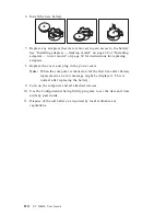
Page 76: ...4 Rotate the power supply toward you slightly 62 PC 300GL User Guide...

Page 77: ...Pull the power supply forward and carefully rotate it toward the front of the chassis Lay it to the side Power Supply 6 To replace the power supply reverse these steps Chapter 6 Installing options 63...

Page 78: ...e Working with adapters on page 68 When disconnecting cables be sure to note where they attach so you can correctly reattach them later Note For easier access to the system board it helps to place the...

Page 79: ...ry EIDE connector 8 Power connector 9 Fan connector 1 Battery 11 Wake on LAN connector 12 PC PCI legacy audio adapter 13 Clear CMOS recovery jumper 14 PCI adapter slot 4 15 PCI adapter slot 3 16 PCI a...

Page 80: ...arts on the system board on page 64 Before you begin Read Safety information on page vii and Handling static sensitive devices on page 53 Read the instructions that come with the new system memory Tur...

Page 81: ...u removed it See Installing adapters desktop model on page 68 or Installing adapters tower model on page 69 for instructions to reinstall the adapter 6 Reinstall the power supply if you removed it Wha...

Page 82: ...13 inches long in the desktop model and 228 mm 9 inches long in the tower model Installing adapters desktop model Before you begin Read Safety information on page vii and Handling static sensitive de...

Page 83: ...ystem board on the inside of your computer If your computer comes with a preinstalled IBM Ethernet adapter SWO cable is required for Alert on LAN support 5 Replace the cover and continue with Configur...

Page 84: ...ake on LAN supported network adapter attach the Wake on LAN cable that came with the adapter to the Wake on LAN connector on the system board If you also want to take advantage of the Alert on LAN fea...

Page 85: ...e devices that your computer uses to read and store data You can add drives to your computer to increase storage capacity and to enable your computer to read other types of media Some of the different...

Page 86: ...Hard Disk Drive Diskette Drive Bay 2 Bay 1 Bay 1 5 25 inch drive Bay 2 5 25 inch drive Bay 3 3 5 inch diskette drive Bay 4 hard disk drive 72 PC 300GL User Guide...

Page 87: ...ted drive electronics IDE drives to the power supply and system board The following cables are provided Four wire power cables connect most drives to the power supply At the end of these cables are pl...

Page 88: ...ts to remember when connecting power and signal cables to internal drives The drives that are preinstalled in your computer come with power and signal cables attached If you replace any drives it is i...

Page 89: ...the computer and all other connected devices Disconnect all external cables and power cords and then remove the computer cover see Removing the cover desktop model on page 55 To install an internal dr...

Page 90: ...ield loose from the drive bay Note To install a 3 5 inch drive into drive bay 2 a 5 25 inch bay you must install a conversion kit For information on purchasing a 3 5 inch conversion kit for a 5 25 inc...

Page 91: ...ovable media drive remove the bay panel from the front bezel and place the bezel frame that came with your computer over the drive bay 7 Connect the power and signal cables to the drive What to do nex...

Page 92: ...bles and power cords and then remove the computer cover see Removing the cover tower model on page 56 To install an internal drive 1 Open the swinging door in front of bays 1 and 2 2 Remove the drive...

Page 93: ...r IBM reseller or IBM marketing representative 4 Install the drive into the bay Align the screw holes and insert the two screws 5 If the drive you installed has nonremovable media such as a hard disk...

Page 94: ...fere with other cables that are connected to the computer Before you begin Obtain the following A 19 mm 3 4 in U bolt and threaded nuts that fit the U bolt A security cable A lock such as a combinatio...

Page 95: ...cured to the building structure or foundation and from which it cannot be removed then fasten the cable ends together with a lock Completing the installation After working with options you need to ins...

Page 96: ...the cover properly these rail guides must engage the metal rails at the bottom of the chassis 4 Lower the cover down over the chassis so that the rail guides engage the rails 5 Slide the cover forward...

Page 97: ...Desktop Tower Chapter 6 Installing options 83...

Page 98: ...uration Setup Utility program For example when you start your computer after adding most internal hard disk drives the settings might be updated If the settings are not updated use the Configuration S...

Page 99: ...e settings that were automatically updated by the system programs After you change an option and restart the computer the following screen might appear POST Startup Error s The following error s were...

Page 100: ...ich it searches devices for the operating system is the startup sequence After adding new devices to the computer you might want to change the startup sequence You can use the Configuration Setup Util...

Page 101: ...you can pass on to a service technician You can check the hardware by following the procedures in this chapter You can also use the diagnostic programs provided with your computer see IBM Enhanced Di...

Page 102: ...because of basic input output system BIOS shadowing in random access memory RAM If POST finishes without detecting any problems the first screen of your operating system or application program appear...

Page 103: ...application or operating system displayed Yes No 002 Continue at Step 004 003 You might have an I O device that is failing or an intermittent problem with your computer Go to IBM Enhanced Diagnostics...

Page 104: ...figuration Setup Utility start automatically after the error message displayed Yes No 011 Follow the action for this error message described in POST errors on page 92 012 Have you recently added remov...

Page 105: ...nfiguration Setup Utility program menu your operating system will start automatically unless there is an unresolved problem with the startup device Important If you did not change any settings in the...

Page 106: ...terrupt failure Have the computer serviced 102 Timer failure Have the computer serviced 106 System board failure Have the computer serviced 110 Parity error Have the computer serviced 111 I O parity e...

Page 107: ...ion 163 Clock not updating Have the computer serviced 164 CMOS RAM memory size does not match Go to IBM Enhanced Diagnostics program on page 108 to run diagnostics 167 Clock not updating Update the BI...

Page 108: ...ollow the instructions to set an administrator password and the startup sequence 190 The computer chassis intrusion detector was cleared This is an informational message No action is required 20x Memo...

Page 109: ...stics program on page 108 3 If the problem persists have the computer serviced 762 Math coprocessor configuration error Have the computer serviced 11xx Serial port error xx serial port number Have the...

Page 110: ...ou to distinguish the beeps For the following beep codes the numbers indicate the sequence and number of beeps For example a 2 3 2 error symptom a burst of two beeps three beeps then two beeps indicat...

Page 111: ...checksum failure 1 2 1 Programmable interval timer test failure 1 2 2 DMA initialization failure 1 2 3 DMA page register write read test failure 1 2 4 RAM refresh verification failure 1 3 1 First 64...

Page 112: ...tegories in the troubleshooting charts Problem type Go to Diskette Drive Diskette drive problems on page 99 General General problems on page 102 Intermittent Intermittent problems on page 102 Keyboard...

Page 113: ...e startup sequence Use the Configuration Setup Utility program to verify this 3 The diskette you are using is good and not damaged Try inserting another diskette if you have one 4 The diskette is inse...

Page 114: ...Turn off the monitor Moving a color monitor while it is turned on might cause screen discoloration b Adjust the placement of the monitor and other devices so that they are at least 305 mm 12 in apart...

Page 115: ...es on page 10 2 The necessary device drivers for the application programs are installed If you cannot correct the problem have the computer serviced The monitor works when you turn on the system but g...

Page 116: ...h as a broken cover lock or indicator lights not working Have the computer serviced Intermittent problems Action A problem occurs only occasionally and is difficult to detect Verify that 1 All cables...

Page 117: ...you cannot correct the problem have the computer serviced The mouse or pointing device does not work Verify that 1 The mouse or pointing device cable is securely attached to the proper connector on t...

Page 118: ...ith memory on page 66 for instructions on adding DIMMs 2 The DIMMs are properly installed and securely connected 3 If you added or removed memory you saved the new configuration before exiting the Con...

Page 119: ...vided enough hardware resources for the adapter to function correctly See the documentation supplied with the adapter as well as the documentation for any other installed adapters to determine the res...

Page 120: ...ore information see your SCSI documentation If you cannot correct the problem have the computer serviced Parallel port problems Action Parallel port cannot be accessed Verify that 1 Each port is assig...

Page 121: ...n IBM printer signal cables might cause unpredictable problems 3 You have assigned the printer port correctly in your operating system or application program 4 You have assigned the printer port corre...

Page 122: ...m memory requirements needed to use the software See the information supplied with the software to verify memory requirements Note If you have just installed an adapter or memory you might have a memo...

Page 123: ...ntly selected as the First Startup Device Then write down the devices selected as Second Startup Device Third Startup Device and Fourth Startup Device You must restore these settings when you finish r...

Page 124: ...Where filename is the name of the file you downloaded from the Web To create an IBM Enhanced Diagnostics diskette from the Software Selections CD 1 If the Access IBM program is not already open click...

Page 125: ...er from a remote location To use CoSession this program must be installed in your computer and your computer must have a modem or a LAN connection Important Before attempting to use CoSession contact...

Page 126: ...he cover desktop model on page 55 and Removing the cover tower model on page 56 12 Remove any adapters that impede access to the BIOS Configuration jumper 13 Move the Clear CMOS recovery jumper to its...

Page 127: ...d accumulators that contain heavy metals must not be disposed of with normal domestic waste They will be taken back free of charge by the manufacturer distributor or representative to be recycled or d...

Page 128: ...ce the cover and plug in the power cord Note When the computer is turned on for the first time after battery replacement an error message might be displayed This is normal after replacing the battery...

Page 129: ...n Workstations U S http www ibm com pc us accessories Options by IBM U S http www ibm com pc us netfinity IBM Netfinity Servers U S You can select a country specific Web site from these pages Help is...

Page 130: ...se to obtain warranty service Please have the following information ready when you call Machine Type and Model Serial numbers of your IBM hardware products Description of the problem Exact wording of...

Page 131: ...ing system or application program Getting customer support and service Purchasing an IBM PC hardware product entitles you to standard help and support during the warranty period If you need additional...

Page 132: ...Bulletin boards and online information services provide assistance through question and answer message areas live chat rooms searchable databases and more Technical information is available on a wide...

Page 133: ...y problems can be remotely diagnosed and corrected quickly and easily In addition to a modem a remote access application program is required This service is not available for servers There might be a...

Page 134: ...n information for your system If possible be at your computer when you call In the U S and Canada these services are available 24 hours a day 7 days a week In the U K these services are available Mond...

Page 135: ...Zealand call 61 2 9354 4171 In all other countries contact your IBM reseller or IBM marketing representative Purchasing additional services During and after the warranty period you can purchase additi...

Page 136: ...t package or as an annual contract with a 10 incident limit For more information about purchasing Enhanced PC Support see Ordering support line services on page 123 900 number operating system and har...

Page 137: ...ort In Canada contact IBM Direct at 1 800 465 7999 or 1 Call 1 800 465 3299 2 Select the HelpWare catalog In all other countries contact your IBM reseller or IBM marketing representative For more info...

Page 138: ...Agreements Availability of the services varies by product For more information about warranty upgrades and extensions In the U S call 1 800 426 4968 In Canada call 1 800 465 7999 In all other countri...

Page 139: ...D your operating system must be installed in your computer You can use the CD to Install some software products directly from the CD on models equipped with a CD ROM drive Create an image of the IBM S...

Page 140: ...m is installed you can access it through the Programs choice on the Windows Start menu For most programs support documentation is built into the online Help system for some online documentation is als...

Page 141: ...access it through the Programs choice on the Windows Start menu For most programs support documentation is built into the online Help system for some online documentation is also provided Appendix A...

Page 142: ...128 PC 300GL User Guide...

Page 143: ...e following information The model and type M T numbers and the serial number S N for your computer are located on a label on the rear of the computer Device records Use the following tables to keep a...

Page 144: ...ssor Intel MHz Parallel Connector Serial Connector A Serial Connector B USB Connector 1 USB Connector 2 Monitor Connector Audio Connectors Keyboard Connector 104 key keyboard Other Mouse Connector Scr...

Page 145: ...t for resale from IBM or your reseller The term Machine means an IBM machine its features conversions upgrades elements or accessories or any combination of them The term Machine does not include any...

Page 146: ...nt modification unsuitable physical or operating environment improper maintenance by you or failure caused by a product for which IBM is not responsible The warranty is voided by removal or alteration...

Page 147: ...art that replaces a removed part will assume the warranty service status of the removed part Before IBM or your reseller exchanges a Machine or part you agree to remove all features parts options alte...

Page 148: ...ATA OR 3 SPECIAL INCIDENTAL OR INDIRECT DAMAGES OR FOR ANY ECONOMIC CONSEQUENTIAL DAMAGES INCLUDING LOST PROFITS OR SAVINGS EVEN IF IBM ITS SUPPLIERS OR YOUR RESELLER IS INFORMED OF THEIR POSSIBILITY...

Page 149: ...e repair and exchange service for the Machine without charge under the type of service designated for the Machine and will manage and install engineering changes that apply to the Machine If a Machine...

Page 150: ...ur reseller replaces becomes its property and the replacement becomes yours You represent that all removed items are genuine and unaltered The replacement may not be new but will be in good working or...

Page 151: ...egardless of the basis on which you are entitled to claim damages from IBM including fundamental breach negligence misrepresentation or other contract or tort claim IBM is liable for no more than 1 da...

Page 152: ...this paragraph apply PEOPLE S REPUBLIC OF CHINA Governing Law The following is added to this Statement The laws of the State of New York govern this Statement INDIA Limitation of Liability The follow...

Page 153: ...is provided in Albania Armenia Belarus Bosnia and Herzegovina Bulgaria Croatia Czech Republic Federal Republic of Yugoslavia Georgia Hungary Kazakhstan Kirghizia Former Yugoslav Republic of Macedonia...

Page 154: ...and two of the first paragraph of this Section 1 death or personal injury or physical damage to your real property solely caused by IBM s negligence and 2 the amount of any other actual direct damages...

Page 155: ...em is added to this paragraph 3 breach of IBM s obligations implied by Section 12 of the Sale of Goods Act 1979 or Section 2 of the Supply of Goods and Services Act 1982 Applicability of suppliers and...

Page 156: ...apable of correctly processing providing and or receiving date data within and between the 20th and 21st centuries provided all other products for example software hardware and firmware used with the...

Page 157: ...e Windows logo are trademarks of Microsoft Corporation in the United States and or other countries Other company product and service names may be trademarks or service marks of others Alert on LAN Ass...

Page 158: ...does cause harmful interference to radio or television reception which can be determined by turning the equipment off and on the user is encouraged to try to correct the interference by one or more of...

Page 159: ...ial environment This equipment generates uses and can radiate radio frequency energy and if not installed and used in accordance with the instruction manual may cause harmful interference to radio com...

Page 160: ...ates relating to electromagnetic compatibility IBM cannot accept responsibility for any failure to satisfy the protection requirements resulting from a nonrecommended modification of the product inclu...

Page 161: ...nce trouble with this product contact your authorized reseller or call IBM In the United States call IBM at 1 800 772 2227 In Canada call IBM at 1 800 565 3344 You may be required to present proof of...

Page 162: ...protection that the electrical ground connections of the power utility telephone lines and internal metallic water pipe system if present are connected together This precaution may be particularly imp...

Page 163: ...nnement Pour sa propre protection l utilisateur doit s assurer que tous les fils de mise la terre de la source d nergie lectrique des lignes t l phoniques et des canalisations d eau m talliques s il y...

Page 164: ...8 AWG Type SVT or SJT three conductor cord a maximum of 15 feet in length and a parallel blade grounding type attachment plug rated 15 amperes 125 volts For units intended to be operated at 230 volts...

Page 165: ...n Sudan Sweden Syria Togo Tunisia Turkey former USSR Vietnam former Yugoslavia Zaire Zimbabwe 13F9997 Denmark 14F0015 Bangladesh Burma Pakistan South Africa Sri Lanka 14F0033 Antigua Bahrain Brunei Ch...

Page 166: ...152 PC 300GL User Guide...

Page 167: ...tomatic power on modem ring detect 43 PCI wake up 43 serial port ring detect 42 setting 43 wake on LAN 43 automatic power on continued wake up on alarm 43 automatic startup sequence setting 38 B backi...

Page 168: ...data channel 26 Desktop Management Interface DMI 24 desktop models 2 device drivers 84 device drivers video 25 device security 32 DHCP description 23 diagnostic CD ROM 108 charts 97 diskettes 108 err...

Page 169: ...ducing 17 graphics adapters 25 58 64 H handling static sensitive devices 53 hard disk drive 73 hard disk drives adding 53 backing up 51 power management 42 supported 4 hardware identifying parts 64 he...

Page 170: ...ing 66 location on system board 58 64 types 66 microprocessor 4 modem ring detect 43 serial port ring detect 42 monitor care of 17 connector 10 DDC standard 26 disable mode 42 flicker 26 off mode 41 p...

Page 171: ...and Play adapters 84 technology 5 pointing device problems 103 ports 10 55 57 84 POST at startup 19 description of 88 updating 27 POST BIOS updates 39 power cord 18 150 management 40 output 5 power ca...

Page 172: ...computer 29 Setup Utility See configuration setup utility program shutting down computer 20 signal cables for internal drives 73 software errors 108 preinstalled 6 problems 108 solving problems 87 11...

Page 173: ...rt 10 utility program setup 84 V venting of hot air 17 VGA video graphics array 25 video adapters 25 58 64 controller 4 25 device drivers 25 modes 25 SVGA 25 VGA 25 video memory 66 video port 10 volta...

Page 174: ...IBM Part Number 37L2165 Printed in U S A July 1999 37L2165...

Reviews: