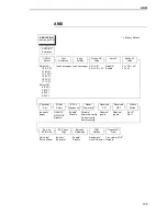
background image

ANSI

 199

Page Format

Margins

Left Margin. Defines where the first print column is located. The left 
margin is specified as the number of characters from the left edge of the 
form.

Right Margin. Defines where the last print column is located. The right 
margin is specified as the number of characters from the right edge of the 
form. 

Top Margin. Defines the location of the first print line on the page. The 
top margin is specified as the number of lines from the top of the form's 
position.

Bottom Margin. Defines the location of the last print line on the page. 
The bottom margin is specified as the number of lines from the bottom of 
the form's position.

Form Length

Specifies the form length in lines. The maximum form length in lines depends 
on the current LPI setting; it is equal to the maximum form length in inches 
multiplied by the current LPI setting. For example, at 6 LPI the maximum form 
length is 6 LPI x 24 inches = 144 lines.

Only valid form length values will be accepted. If you select a length that is 
larger than the maximum length for the current LPI, the maximum length will 
be used. If you need a longer page length, you must first change the LPI. The 
default is 66 lines.
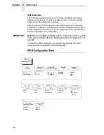
IMPORTANT

If the form length is set in lines and you change the LPI, the effective 
page length changes to the form length in characters divided by the new 
LPI.

NOTE: Receipt of a data stream control code which changes the form length 

overrides the form length previously specified via the operator panel.

Form Width

Allows you to input the form width in characters from 1 through 272. The 
maximum form width in characters depends on the current CPI setting; it is 
equal to the maximum form width in inches multiplied by the current CPI 
setting. 

Only valid form width values will be accepted. If a width is selected that is 
larger than the maximum width for the current CPI, then the maximum width 
will be used. If a larger width value is desired, then the CPI value must be 
changed first. The default is 136 lines.

Summary of Contents for 6400-i05

Page 1: ...Setup Guide Cabinet and Pedestal Models 6400i Line Matrix Printers S544 5640 04 ...

Page 2: ......

Page 3: ...S544 5640 04 Setup Guide Cabinet and Pedestal Models 6400i Line Matrix Printers ...

Page 4: ...nts by fax to 1 800 524 1519 USA only or 1 303 924 6873 by E mail to printpub us ibm com or by mail to IBM Printing Systems Division Department H7FE Building 004M Information Development PO Box 1900 Boulder CO 80301 9191 USA IBM may use or distribute whatever information you supply in any way it believes appropriate without incurring any oblication to you Copyright International Business Machines ...

Page 5: ...er 4 Do not connect or disconnect any communication port teleport attachment connector or power cord during an electrical storm 5 Power off the printer and disconnect the power cord before connecting or disconnecting any communication port teleport or attachment cable connector DANGER This product is equipped with a 3 wire power cord and plug for the user s safety Use this power cord in conjunctio...

Page 6: ......

Page 7: ... Site 28 Printer Dimensions 29 Printer Component Locations 31 Remove Shipping Restraints Cabinet Model 33 Remove The Cardboard Packing And Envelope 34 Remove The Hammer Bank Protective Foam 35 Remove The Platen Protective Foam 37 Remove Wood Blocks 38 Adjust The Paper Supports 39 Release The Paper Chains Cabinet Model 40 Remove Tags Cabinet Model 41 Remove The Shipping Restraints From The Power Pa...

Page 8: ...orm 77 Test The Printer 78 3 Configuring the Printer 79 Overview 79 The Configurations 79 Active Versus Saved Configurations 80 The Configuration Main Menu 80 Using The Operator Panel 83 Program Mode 84 Unlocking The Program Mode 84 Locking The Program Mode 84 Entering Program Mode 85 Printing The Current Configuration 85 Factory Default Configuration Values 87 Changing Parameters 92 Saving Your C...

Page 9: ...172 Dataproducts Menu 175 IEEE 1284 178 Serial Interface Menu 180 Emulation Configuration Menu 186 IPDS Feature 187 IPDS Configuration Menu 188 ANSI 195 IGP Feature PGL 203 IGP Emulation Menu 204 Code V Feature VGL 209 Code V Emulation Menu 210 Printer Emulation Configuration Menu 219 Proprinter III XL Emulation Menu 220 Epson Emulation Menu 222 P Series Emulation Menu 224 P Series XQ Emulation Me...

Page 10: ...Signals 258 Dataproducts Parallel Interface Configuration 258 IEEE 1284 Parallel Interface 259 Operating Modes 259 The Negotiation Phase 260 Signals 260 Terminating Resistor Configurations 263 6 Routine Service and Diagnostics 265 Overview 265 Cleaning Requirements 265 Cleaning The Outside Of The Cabinet 265 Cleaning Inside The Cabinet 266 Printer Self Tests 269 Running The Printer Self Tests 270 ...

Page 11: ...r 311 Attaching Printer to an iSeries or zSeries Host System 311 Attaching Printer to an iSeries Host System 311 Attaching Printer to an iSeries with Twinax Interface 311 Changing Your iSeries Printer Configuration 312 Attaching Printer to Remote Control Unit with Twinax Interface 314 Attaching Printer to an IBM System 36 with Twinax Interface 315 Attaching Printer to zSeries Systems 316 Types of ...

Page 12: ...nit Types 325 Physical Unit PU types and examples 325 Summary of LU Types and Representative IBM Products 326 Notices 329 Energy Star 329 Notices 329 Trademarks 331 Product Recycling and Disposal 332 Communication Statements 333 Glossary 337 ...

Page 13: ...n The word Danger next to the lightning slash indicates the presence of a hazard that could cause death or serious personal injury Danger and Caution notices are numbered to help you find the translated versions in the IBM 6400 Safety Notices booklet The word Caution next to the exclamation point indicates the presence of a hazard that could cause moderate or minor personal injury The word Caution...

Page 14: ...d maintenance Conventions In This Setup Guide Key names indicator names and messages that appear on the operator panel display are capitalized as they actually appear on the printer Key names are shown in bold Example Press the CLEAR key then press the ON LINE key Quotation marks indicate messages on the Liquid Crystal Display LCD For example Example Press the ON LINE key OFFLINE appears on the LC...

Page 15: ...formation used with the optional IGP emulation enhancement feature Code V Programmer s Reference Manual Provides information used with the optional Code VTM emulation enhancement feature ANSI Programmer s Reference Manual Provides host control codes and character sets for the ANSI emulation IPDS Twinax Emulation Programmer s Reference Manual Provides an overview of Intelligent Printer Data StreamT...

Page 16: ... XQ Serial Matrix and Proprinter III XL emulations Coax Twinax IPDSTM ANSI and the IGP PGL and IGP VGL graphics enhancement emulations are available as optional upgrades No matter what emulation is installed your printer is easy to use The message display and lights on the control panel communicate with you directly and clearly You can select every function on your printer at the control panel or ...

Page 17: ...es per minute lpm i5P for 500 lpm and i1P for 1000 lpm The 6400 i5P and i1P models are pedestal models with the QuickAccess Cover installed The 6400 i20 i2s and i24 models are available with the power stacker option installed Refer to the following table for a complete listing of model numbers and options Table 1 6400 i05 i5P i10 i1P i15 i20 i2s i24 Printers Model Number Print Speed Cabinet Pedest...

Page 18: ...erfaces RS 232 Serial RS 422 Serial PC Parallel Dataproducts Parallel Ethernet Interface IEEE 1284 Coax Twinax features are available with this printer IBM Coax Twinax Printer Emulations Each emulation provides a different set of configuration menus control codes and character sets The following printer emulations or protocols are standard and selectable at the operator panel Proprinter III XL Emu...

Page 19: ...r but incorporates several systems into one emulation This emulation enables a line matrix printer to print files coded for a serial matrix printer and is sometimes referred to as the Serial Matrix collection IMPORTANT This emulation appears as Serial Matrix on the operator panel NOTE Serial matrix refers to the way printer characters are formed A moving printhead uses pins to form whole character...

Page 20: ...zed shadow printing Automatic underlining and overscoring Superscript and subscript printing Double high and wide printing Resident multinational character sets Graphics And Vertical Formatting Several graphics and vertical formatting features are available Three built in graphics generators IBM Proprinter III XL bit image graphics Epson FX dot graphics mode P Series Plot Programmable electronic v...

Page 21: ...uch as the IBM 3262 Models 3 and 13 IBM 4234 Models 1 2 and 9 and IBM 5224 Models 1 and 2 This feature can be used with the Intelligent Printer Data Stream IPDS feature which is described below IBM Intelligent Printer Data Stream Coax Twinax Provides the ability to create forms overlays and graphics IPDS also provides compatibility when replacing printers such as the IBM 4234 Models 12 and 11 This...

Page 22: ...e is necessary if you are using the Dataproducts parallel protocol Ethernet Interface Enables you to attach your printer to Local Area Networks using Ethernet protocols The Ethernet Interface functions as a workstation server on your network enabling your users to submit print jobs to your printer Power Paper Stacker Mechanically directs the paper from the printer to the paper stacking area This f...

Page 23: ...X emulation mode There are additional emulations that are provided as optional features such the Code V and IGP emulations For additional information refer to Code V Feature VGL on page 209 and IGP Feature PGL on page 203 Graphics Enhancements The PGL and Code V emulations allow you to create and store forms generate logos bar codes expanded characters and create other graphics Alphanumeric and ba...

Page 24: ...24 Chapter 1 The IBM 6400 Printer Family ...

Page 25: ... README 1ST file on the Configuration Utility diskette NOTE The Configuration Utility diskette contains a README 1ST file that describes the contents of the diskette AIX print drivers and configuration information for replacing existing IBM printers In addition there might be another file called README TXT that contains information that was added after the printer documentation was printed 4 Do no...

Page 26: ... ordered a communications cable see page 297 7 Configure the printer to work with host systems and to match your emulation such as IBM Proprinter III XL Follow the instructions provided in Chapter 3 Configuring the Printer and review the information provided in Appendix C Host Attachment NOTE If you are replacing an printer with this printer make sure you review the information on the Configuratio...

Page 27: ...The printer automatically senses and adjusts itself to conform to the correct voltage range Primary circuit protection is provided by the power switch which is also a circuit breaker Consult an electrician if printer operation affects local electrical lines See Electrical Characteristics on page 294 for additional power specifications IMPORTANT Printer power should be supplied from a separate AC c...

Page 28: ...onform to the correct voltage range Is relatively dust free Has a temperature range of 10 C to 40 C 50 F to 104 F and a relative humidity from 15 to 90 non condensing Is located within the maximum allowable cable length to the host computer This distance depends on the type of interface you plan to use as shown in Table 2 Table 2 Maximum Interface Connection Cable Length Interface Type Maximum Cab...

Page 29: ...t Model With Power Paper Stacker Printer Dimensions 27 0 in 68 84 cm 83 0 in 210 8 cm 29 0 in 73 7 cm 27 0 in 68 6 cm 27 0 in 68 6 cm 41 0 in 104 cm 57 5 in 146 1 cm 27 0 in 68 6 cm 83 0 in 210 8 cm 32 5 in 82 6 cm 27 0 in 68 6 cm 27 0 in 68 6 cm 32 0 in 81 3 cm 42 5 in 107 8 cm 59 0 in 149 9 cm Printer Dimensions ...

Page 30: ...30 Chapter 2 Printer Dimensions Figure 3 Exploded View Of Pedestal Model Printer Dimensions 25 in 63 5 cm 10 5 in 26 67 cm 48 0 in 122 cm 30 in 76 2 cm 24 6 in 62 48 cm ...

Page 31: ...st of the installation procedures Figure 4 6400 Series Models Printer Component Locations with Ribbon Spools Exploded Above Ribbon Spool Hub Latch Tractor Lock Paper Scale Splined Shaft Paper Support Tractor Vertical Position Knob Forms Thickness Lever Ribbon Guide Ribbon Path Loading Diagram Hammer Bank Cover and Ribbon Mask Base Casting Printer Component Locations ...

Page 32: ... with Open Access Cover and Ribbon Spools Exploded Above Ribbon Spool Shuttle Cover Assembly Ribbon Hub Hub Latch Ribbon Guide Forms Thickness Lever Splined Shaft Adjustable Hinge Adjustable Paper Guide Printer Cover Operator Panel Tractor Tractor Lock Tractor Door Hammerbank Cover Ribbon Mask ...

Page 33: ...aterial Cardboard packing protective foam and tie wraps protect printer mechanisms from possible damage during shipment You must remove these shipping restraints before you operate the printer Save the cardboard packing and protective foam with the other packing materials To avoid shipping damage reinstall the shipping restraints whenever the printer is moved or shipped To reinstall the shipping r...

Page 34: ...e the cardboard packing 3 Open the tractor doors 4 Push the tractor locks down 5 Slide the tractors outward as far as they will go The forms thickness lever should be in the fully open raised position 6 Remove the envelope that contains the sample configuration printout 7 Store this in the pouch that is attached to the left interior side of the cabinet Envelope Cardboard Packing 2 Forms Thickness ...

Page 35: ... Hammer Bank Protective Foam 6400 Series Models 1 Slide the paper supports outward as far as they will go 2 Lift the hammer bank protective foam and remove it from between the ribbon mask and the platen 3 Rotate the forms thickness lever downward to position A Hammer Bank Protective Foam Paper Supports 2 Forms Thickness Lever ...

Page 36: ...d View of Removal of the Hammer Bank Protective Foam i20 i2s and i24 Models i20 i2s i24 Models 4 Cut the tie wrap and remove it from the side plate 5 Lift the hammer bank protective foam and remove it from between the ribbon mask and the platen Hammer Bank Protective Foam ...

Page 37: ...6400 Series Models 1 Rotate the forms thickness lever downward to position A 2 Rotate the platen protective foam toward the front of the printer and out from under the support shaft 3 Remove the platen protective foam NOTE The 6400 i20 i2s and i24 models do not have a platen protective foam Platen Protective Foam Forms Thickness Lever ...

Page 38: ...ints Cabinet Model Remove Wood Blocks Figure 10 Cover Front and Back Door Cabinet Open Showing the Removal of Six Wood Blocks 1 Remove the six wood blocks NOTE Make sure the tape securing the wood blocks is removed entirely Wood Blocks 6 ...

Page 39: ...er Supports Figure 11 Paper Supports With Directional Arrows Showing the Adjustment Capabilities 6400 Series Models Slide the paper supports inward until they are approximately four inches from the tractor doors Tractor Doors 2 Paper Supports 2 ...

Page 40: ...u have the power paper stacker installed skip this procedure and go to Remove The Shipping Restraints From The Power Paper Stacker on page 42 1 Open the cabinet rear door 2 Cut the tie wraps and release the paper chains from the bags at the top rear of the printer frame Remove the tie wraps and bags 3 Make sure each chain hangs freely with no kinks or knots Tie Wraps 2 Paper Chains 8 Bags 2 ...

Page 41: ...lled skip this procedure and go to Remove The Shipping Restraints From The Power Paper Stacker on page 42 1 Remove the tie wrap attached to the passive stacker paper fence The tie wrap is marked with a large red tag 2 Close the cabinet rear door Tie Wrap Red Tag Passive Stacker Paper Fence Tie Wrap Red Tag Passive Stacker Paper Fence 1000 1500 2000 2400 lpm model 500 lpm model ...

Page 42: ...nter Special packaging protects the power stacker mechanisms from damage during shipment This section describes how to remove the shipping restraints before you operate the printer Save the packaging materials You will need to reinstall them if you decide to move or ship the printer To reinstall the packaging materials reverse the steps in this section IMPORTANT To avoid shipping damage install th...

Page 43: ...aps 3 Raise the paper guide to its highest position by hand 4 Remove the plastic bags from the paper chains 5 Verify that both fences are in the down position Figure 15 View of the Pull Out Drawer Illustrating Placement of the Paper Tent 6 Remove unwrap and replace the paper tent onto the pull out drawer Paper Tent ...

Page 44: ... this section Remove the Protective Film and Envelope Figure 16 Pedestal Model with Cover Open Showing Removal of the Operator Panel Message Display Protective Film and Sample Configuration Printout Envelope 1 Raise the printer cover 2 Carefully peel off the tape and lift the protective film off the operator panel message display 3 Open the tractor doors 4 Push the tractor locks down 5 Slide the t...

Page 45: ... Figure 17 Pedestal Model with Cover Open Showing Removal of the Hammer Bank Protective Foam 1 Slide the paper supports outward as far as they will go 2 Lift the hammer bank protective foam and remove it from between the ribbon mask and the platen Hammer Bank Protective Foam Paper Supports ...

Page 46: ...ith Cover Open Showing Removal of the Platen Protective Foam 1 Rotate the forms thickness lever downward to position A 2 Rotate the platen protective foam toward the front of the printer and out from under the support shaft 3 Remove the platen protective foam Platen Protective Foam Support Shaft Forms Thickness Lever ...

Page 47: ... of the support shaft Position them so that they divide teh space between the tractors into three approximately equal segments 2 Place the output basket in the holes in the back of the printer 3 Screw the ground wire attached to the output basket to the printer 4 Place the input paper shelf optional feaure in the holes in the front of the pedestal base p5coutry A A Output Basket Screw Ground Wire ...

Page 48: ...straints Pedestal Model Remove Tags Pedestal Model Figure 20 View of the Pedestal Model Showing Removal of the Tie Wrap Remove the tie wrap attached to the output basket It is marked with a large red tag Tie Wrap Red Tag Output Basket ...

Page 49: ...r and using them soon after printing Forms will not stack in top exit mode Setting Top Paper Exit 1 Press Stop to place the printer in NOT READY state If there is paper in the printer unload the paper then continue with step 2 of this procedure Figure 21 Underview of the Right Rear Pedestal Cover Showing Adjustment of the Hinge Thumbscrews 2 Open the printer cover 3 Loosen the two hinge adjustment...

Page 50: ...t Options 5 Tighten the two hinge adjustment thumbscrews 6 Slide the paper guide slightly to the left and raise it to its upper position for the top exit Figure 23 Top Back View of the Pedestal Model with Paper Exiting through the Top Paper Exit 7 Load the paper see page 66 feeding it out the top paper exit Top Paper Exit Paper ...

Page 51: ...his procedure Figure 24 Loosening the Hinge Thumbscres Open View of the Back Rear Pedestal Model Cover 2 Open the printer cover 3 Loosen the two hinge adjustment thumbscrews 4 Slide the cover forward until it stops Figure 25 Internal View of the Pedestal Model Showing Paper Exit Options 5 Tighten the two hinge adjustment thumbscrews 6 Place the paper guide in its lower position Thumbscrew ...

Page 52: ... remove and open the cardboard box containing the power cord printer ribbon and operator panel overlay label Refer to Printer Specifications on page 289 for recommended cables Documentation is stored in a pouch container on the left interior side of the cabinet 1 Before powering on the printer ensure the printer is plugged into an appropriate power source Refer to page 27 for information on the pr...

Page 53: ...er cord into the printer AC power connector then into the AC power outlet Figure 27 Internal Back View of the Cabinet Model Showing Interface and Power Cable Connections NOTE 1 The Dataproducts adapter feature attaches to the PC Parallel interface connector 2 Twinax Coax and Ethernet Interfaces appear only if these features are installed Power Switch AC Power Connector AC Power Cable Cable Routing...

Page 54: ...k View of the Cabinet Model Showing Product Description Label Location 1 Check the product description label to verify that the voltage source at the printer site conforms to the requirements specified on page 28 Figure 29 Power Switch Turned OFF 2 Make sure the printer switch is set to OFF ...

Page 55: ...ected Figure 31 Bottom Rear Inside View of the Cabinet Model Showing the Cable Routing Notch 5 Locate the notch in the lower left corner of the back of the cabinet 6 Hold the I O cable below its connector and gently push the cable through the opening in the grommet seated in the notch I O Cover I O Connector 6ci o cabl I O Cable Grommet Connect The Interface And Power Cables Cabinet Models ...

Page 56: ...tor to the printer I O connector 9 Secure the cable to the printer using the two cable standoffs Figure 33 Open Cabinet Front Door Showing the Printer Accessories Package 10 Open the cabinet front door and cut the strap that secures the box which contains the power cord printer ribbon control panel overlay labels and documentation 11 Open the box and remove the power cord overlays and documentatio...

Page 57: ...k corner of the cabinet 13 Thread the power cord inside the bracket where the gas spring is attached Figure 35 Rear Inside View Cabinet Model Showing Power Cord Attachment 14 Plug the power cord into the printer AC power connector then into the AC power outlet 6cprcrd Power Cord 6cprcrd2 AC Power Connector Power Cord Connect The Interface And Power Cables Cabinet Models ...

Page 58: ...anel overlay label Refer to Cables on page 297 for recommended cables 1 Before powering on the printer ensure the printer is plugged into an appropriate power source Refer to page 27 for information on the proper source 4 Do not connect or disconnect any communication port teleport attachment connector or power cord during an electrical storm 5 Power off the printer and disconnect the power cord b...

Page 59: ...rface 4 Remove the cover from the I O connector you have selected p6cprswt Parallel Connector Auxiliary I O Serial Connector AC Power Connector NOTE 1 The Dataproducts adapter feature attaches to the PC Parallel interface connector 2 Twinax Coax and Ethernet Interfaces appear only if these features are installed Power Switch On Off A A I O Connector Connect The Interface And Power Cables Pedestal ...

Page 60: ...ter Interface Showing Cable Connector Attachment 5 Attach the cable connector to the printer I O connector Figure 39 View of the Power Cord Attachment 6 Plug the power cord into the printer AC power connector then into the AC power outlet Cable Connector I O Connector PC Power Outlet Power Cord ...

Page 61: ... O Adapter NOTE Centronics is not present on Network based models Dataproducts Standard Adapter Serial RS 232 RS 422 Auxiliary I O Diagnostic Centronics Ethernet Pedestal Models Cabinet Models Ethernet Auxiliary I O Diagnostic Serial RS 23 Centronics Connect The Interface And Power Cables Pedestal Models ...

Page 62: ...verlay Label 1 Choose the overlay labels in the appropriate language 2 Attach the operator panel overlay label by adhering it to your operator panel Network 10 100Base T Coax Twinax Dataproducts Long Line Power Ready Processing Attention Menu Scroll Enter Scroll Printer Config uration Return Micro Micro Line Feed View Start Stop Form Feed Set Top of Form Cancel Eject Restore ...

Page 63: ...tle cover for the following steps Figure 43 Cabinet and Pedestal Models with the Printer Cover Open 1 Open the printer cover 2 Pedestal models pull the operator panel up and out of the way The operator panel can be pulled toward you to provide clearance Cabinet Model Pedestal Model Install The Ribbon ...

Page 64: ...7 With the ribbon supply to the outside squeeze the right hub latch and place the full spool on the right ribbon hub 8 Press the spool down until the hub latch snaps into place NOTE The ribbon must not be twisted A twisted ribbon can lower print quality shorten ribbon life and cause paper or ribbon jams If you are installing a Clean Hands ribbon identified by a long metalic leader the leader will ...

Page 65: ... guide 10 Place the empty spool on the left hub 11 Press the spool down until the hub latch snaps into place 12 Turn the left spool by hand and check to ensure that the ribbon tracks correctly in the ribbon path and around the ribbon guides NOTE Printers with the Clean Hands ribbon automatically load the ribbon when the first print job is sent 13 Close the forms thickness lever Cabinet Models Pede...

Page 66: ...binet and Pedestal Models with Printer Cover Open 1 Open the printer cover Figure 48 View of the Forms Thickness Lever in the Raised Position 2 Raise the forms thickness lever as far as it will go 3 Open the tractor doors Forms Thickness Lever Tractor Door ...

Page 67: ...r of the cabinet c Align the paper supply with the front label on the floor of the printer d Ensure that the paper pulls freely from the box Figure 50 Side View of the Cabinet and Pedestal Models Paper Feed Pedestal models a Place the paper supply on the floor in front of the printer or on the optional paper shelf if attached b Ensure that the paper pulls freely from the box Label Paper Slot Paper...

Page 68: ...om slipping down through the paper slot while pulling it through from above with your other hand 7 Pull the paper above and behind the ribbon mask which is a silver metal strip with a clear plastic edge protector Refer to the ribbon path diagram on the shuttle cover Figure 51 View of Paper Loaded Onto the Left Tractor with Door Closed and Tractor Lock Lowered 8 Load the paper onto the left tractor...

Page 69: ...h the number 1 on the paper scale Figure 52 View of the Paper Scale Used as a Guide 10 If adjustment is necessary a Unlock the left tractor b Slide the tractor until it is directly to the left of the number 1 on the paper scale and lock it You can also use the paper scale to count columns Paper Paper Scale Tractor Tractor Splined Shaft Load The Paper ...

Page 70: ...3 Close the tractor door 14 Make sure the leading edge of the first sheet of paper is parallel to the tractor splined shaft If the paper is misaligned reload it onto the tractor sprockets until its edge is parallel to the splined shaft 15 Slide the right tractor to remove the paper slack or to adjust for various paper widths 16 Lock the tractor Right Tractor Door ...

Page 71: ...tial for ribbon damage smeared ink or wavy print 19 Press STOP to remove the LOAD PAPER fault message from the display 20 Press FORM FEED several times to make sure the paper feeds properly beyond the tractors and over the lower paper guide Feed sufficient paper to ensure the paper stacks correctly 21 Close the printer cover 22 Close the cabinet door 23 Press START to place the printer in online m...

Page 72: ...r stacker Power Paper Stacker Component Locations Familiarize yourself with the names and locations of the components shown in the following illustration before operating the power paper stacker Figure 55 View of the Power Paper Stacker Component Locations Pinch Rollers Paper Throat Rear Control Panel Wire Paper Tent Pull Out Paper Tray Bearing Bracket Paper Length Indicator Elevator Disable Switc...

Page 73: ... printer offline 3 Grasp the elevator lift handle and press the elevator disable switch while raising the elevator to the top of its travel Figure 57 Rear View of Cabinet Model Showing Power Stacker Components 4 Make sure the wire paper tent is fitted in the pull out paper tray in the base of the stacker A A Paper Advance Stacker Up Stacker Down Elevator Lift Handle Elevator Disable Switch Wire Pa...

Page 74: ...s an excess of 3 to 5 pages Be certain the paper passes through the paper stacker throat smoothly 2 Stack the 3 5 sheets of paper on top of the wire paper tent making sure the paper lies with the natural folds 3 On the printer s main operator panel the printer displays OFFLINE If a message other than OFFLINE displays in the operator panel refer to Chapter 6 Routine Service and Diagnostics on page ...

Page 75: ...ck that the paper feeds correctly 2 Press the Form Feed key several times to ensure that the paper feeds properly beyond the tractors and over the paper guide assembly 3 Ensure that the paper folds the same way in the stacking area as it does in the supply area 4 Close the front and rear cabinet doors if the length of the form allows Checking The Paper Feed ...

Page 76: ...it Press the Form Feed key several times to ensure that the paper feeds properly beyond the tractors over the paper guide assembly and through the paper exit slot in the rear of the cabinet Ensure that the paper folds the same way in the stacking area as it does in the supply area For top paper exit Press the Form Feed key several times to ensure that the paper feeds properly beyond the tractors o...

Page 77: ...cate the TOF indicator It is the small tab located on the left tractor door 4 Turn the vertical position knob up or down to align the top of the first print line with the TOF indicator For best print quality it is recommended that the top of form be set at least 1 2 inch below the perforation NOTE For exact positioning press the Micro or Micro keys to move the paper vertically in 1 72 inch increme...

Page 78: ...ams with potential for ribbon damage smeared ink or wavy print 7 Press Set Top of Form The paper moves downward to the top of form print position Test The Printer To run an initial printer test print the current configuration page See Printing The Current Configuration on page 85 On the configuration printout examine the print quality of the characters They should be fully formed and of uniform de...

Page 79: ...ation parameters You can configure the printer by pressing operator panel keys or by sending control codes from the host computer This chapter explains how to use the operator panel to change individual parameters and save them as a custom configuration Your programmer s reference manuals provide information about control codes The Configurations A configuration consists of a group of parameters s...

Page 80: ...ion is not lost when you power off the printer NOTE Saved configurations are also referred to as custom sets There are no control codes that allow you to save a parameter in NVRAM However you can save a configuration defined partially by control codes and store it in NVRAM using the operator panel You can also save configuration values using PTR_SETUP see page 111 The Configuration Main Menu Figur...

Page 81: ...mation Print Text Direction Override Host Format Control Maximum Printable Width Hex Print Mode C T Hotport 8 Coax Interface 1 page 126 Print Language Print Character Table Active Print Language PA1 PA2 Buffer Reprint Printer Emulation 9 Early Print Complete SCS Buffer Control Cancel Buffers Hex Transparent Control Mono Dual Case Undefined Character Substitution Print Text Direction Image Buffer S...

Page 82: ...products IEEE 1284 Parallel Hotport Serial Interface page 180 Interface Type Data Protocol Baud Rate Data Bits Stop Bits Parity Data Terminal Ready Request to Send Buffer Size in Kilobytes Poll Character One Char Enquiry Serial Hotport Framing Errors Emulation Configuration page 186 Active Emulation IPDS 3 ANSI 6 IGP Emulation 3 Code V Emulation 3 ASCII Printer Emulation Printer Emulation Configur...

Page 83: ...ion menus As you access menus and options menu names and option values appear on the operator panel message display sometimes referred to as LCD or Liquid Crystal Display This chapter provides numerous examples of how to use the operator panel keys and indicator message display to configure the printer Form Feed Power Ready Processing Attention Menu Micro Printer Con figuration Scroll Micro Scroll...

Page 84: ...cked When Program mode is unlocked pressing the Enter key selects configuration values as the active values that is places them into printer DRAM An asterisk after a displayed setting shows it is entered into memory Press the Scroll Scroll keys at the same time to unlock Program mode The following message will appear briefly Locking The Program Mode When Program mode is locked you cannot use the o...

Page 85: ...tep Key LCD Result Notes 1 Make sure the printer is on 2 Press NOT READY The printer must be in NOT READY mode to print the configuration 3 PRESS START TO PRINT PRESS STOP TO EXIT You are prompted to press the Start key before the configuration prints 4 NOT READY Indicates that the configuration has printed Date and store the printout in a safe place You may also want to label the printout e g Con...

Page 86: ...the installation and configuration of this printer The other options will only be useful once you have modified and saved the printer configuration parameter settings The Power On Custom Set is defined by the Change Power On Set option Custom Sets 1 through 8 are defined by the Save Current Values option These options are described in detail under the Configuration Management Menu description star...

Page 87: ...XXXXXX SHUTTLE TYPE 1500 FLASH 8 MB DRAM 8 MB SECURITY PAL XXXXXX XXX CONFIGURATION CODE FC06FF PRINTER CONTROL Interface Selection Parallel Display Language English Alarm Control Alarm Enabled Print Direction Bidirectional Hex Print Mode Disable Power On State Ready Paper Jam Detection Enable Forms Speed Normal Speed Set Platen at Bottom of Form Disable Shuttle Timeout 5 Seconds Energy Saver Time...

Page 88: ...Data Polarity Standard Strobe Polarity Standard Response Polarity Standard Busy on Strobe Enable Latch Data On Leading Edge Prime Signal Enable TOF Action at Prime Signal Form Feed at Reset Buffer Size in Kilobytes 16 Dataproducts Data Bit 8 Enable PI Ignored Enable Data Polarity Standard Data Request Polarity Standard Strobe Polarity Standard Parallel Hotport Trickle Time 1 4 Sec Timeout 10 Sec R...

Page 89: ...nders Enable Compressed CPI Disable Ignore Character Ignore Mode Disable Select Character 0 IGP100 Compatibility None Expanded Font Block Optimized Ratio Disable ASCII Printer Emulation P Series Emulation Printer Emulation Configurations Proprinter III XL Emulation Print Language 0437 PC Character Set Alternate Character Set PC Character Set 1 Define CR Code CR CR Auto LF Enable Define LF Code LF ...

Page 90: ...ernate Set 80 9F Control Code P Series XQ Emulation Control Code 06 8 0 LPI Define CR Code CR CR Auto LF Disable Define LF Code LF CR LF Compressed Print Char 01 SOH Elong Alt Font Elng BS Font SO High Speed Print Mode Char 02 STX EVFU Select Enable Upper Case Select Disable Slew Relative 1 to 16 Lines Serial Matrix Emulation Character Sets IBM PC Print Language IBM PC Multinational Control Code 0...

Page 91: ...cter Table Print Attributes Proportional Spacing Disable Italic Print Disable Slashed Zero Disable Text Position Bottom of Line Margins Left Margin 0 Characters Right Margin 0 Characters Bottom Margin 0 Lines Perforation Skip Disable Reset Command Load Factory OPERATOR PRINT TESTS Printer Demonstration PRINTER INFORMATION Installed Memory 8 MB Power On Time XXX X Hours Printing Time XX Hours Print...

Page 92: ...xit the configuration menu Printer Control Interface Selection Hex Print Mode Print Direction Alarm Control Display Language Bidirectional Unidirectional Factory Default Step Key LCD Results Notes 1 Determine which parameters you want to change and what the new values will be In this example the value for the PRINT DIRECTION parameter will be changed from BIDIRECTIONAL to UNIDIRECTIONAL 2 Press NO...

Page 93: ...ue An asterisk appears indicating that this choice is now the active value 10 Continue this pattern to make all of the changes using the information in this chapter 11 To save changes so that they will remain when the printer is reset or powered back on see on page 94 If you want to use these values without saving continue to the next step 12 NOT READY Returns the printer to the NOT READY mode 13 ...

Page 94: ...ng configurations You may want to print records of your configurations see page 85 and store them in a safe place such as inside the printer cabinet If you do not save your configuration before you power off the printer all of the new parameter values that have not been saved to NVRAM will be erased When you power the printer on again the power on configuration will load If no configuration has be...

Page 95: ...enu option 5 CONFIGURATION MANAGEMENT RECALL CUSTOM SET Selects the CONFIGURATION MANAGEMENT menu The RECALL CUSTOM SET option appears 6 CONFIGURATION MANAGEMENT SAVE CURRENT VALUES Moves to the SAVE CURRENT VALUES option 7 SAVE CURRENT VALUES 1 Selects the SAVE CURRENT VALUES menu 8 SAVE CURRENT VALUES 2 Scrolls through the list of custom sets 1 8 9 SAVING CONFIGURATION Selects the SAVE CURRENT V...

Page 96: ...o the NOT READY mode 11 OPERATOR MENU LOCKED Locks Program mode and the Operator Menu 12 READY Places the printer in READY mode prepared for normal operation 13 It is recommended you print your current configuration as described on page 85 Step Key LCD Results Notes Stop Scroll Scroll Stop ...

Page 97: ...power off the printer the power on configuration will load the next time the printer is powered on Selecting the power on configuration is explained on page 99 Configuration Management Recall Custom Set Factory Default Custom Set 1 Custom Set 2 Custom Set 3 Custom Set 4 Custom Preloaded Set 5 Custom Preloaded Set 6 Custom Preloaded Set 7 Custom Preloaded Set 8 Protect Custom Sets Change Power On S...

Page 98: ...onfiguration Management menu option 5 CONFIGURATION MANAGEMENT RECALL CUSTOM SET Selects the CONFIGURATION MANAGEMENT menu The RECALL CUSTOM SET option appears 6 RECALL CUSTOM SET FACTORY DEFAULT Moves forward to the FACTORY DEFAULT parameter for the RECALL CUSTOM SET option 7 LOADING SAVED CONFIGURATION Loads the set of Factory Default values The message LOADING SAVED CONFIGURATION appears briefl...

Page 99: ...ower On Custom Set Otherwise the current Power On Custom Set remains selected and the following operator panel message is displayed 042 CUSTOM SET DOES NOT EXIST SAVE FIRST For example if you attempt to change the Power On Custom Set from Custom Set 1 to Custom Set 4 and if Custom Set 4 does not exist Custom Set 1 remains the Power On Custom Set 10 READY Places the printer in READY mode prepared f...

Page 100: ...uration Management menu option 5 CONFIGURATION MANAGEMENT RECALL CUSTOM SET Selects the CONFIGURATION MANAGEMENT menu The RECALL CUSTOM SET option appears 6 CONFIGURATION MANAGEMENT CHANGE POWER ON SET Moves to the CHANGE POWER SET ON parameter 7 CHANGE POWER ON SET FACTORY DEFAULT Displays the first POWER ON SET option FACTORY DEFAULT 8 CHANGE POWER ON SET CUSTOM SET 1 Displays CUSTOM SET 1 as th...

Page 101: ...printer to the NOT READY mode 11 OPERATOR MENU LOCKED Locks Program mode and the Operator Menu 12 READY Places the printer in READY mode prepared for normal operation Step Key LCD Results Notes Stop Scroll Scroll Stop Changing The Power On Configuration ...

Page 102: ...102 Chapter 3 Changing The Power On Configuration ...

Page 103: ...more information about these documents see Related Documents on page 15 The configuration menu diagram on page 104 shows the structure of the configuration menus and the parameter options available in each menu The diagrams list the menus and options in the order they appear when you use the operator panel to configure the printer Factory default configuration values are indicated by an asterisk P...

Page 104: ...ption LAC Approximation Print Text Direction Override Host Format Control Maximum Printable Width Hex Print Mode C T Hotport 8 Coax Interface 1 page 126 Print Language Print Character Table Active Print Language PA1 PA2 Buffer Reprint Printer Emulation 9 Early Print Complete SCS Buffer Control Cancel Buffers Hex Transparent Control Mono Dual Case Undefined Character Substitution Print Text Directi...

Page 105: ...Interface page 180 Interface Type Data Protocol Baud Rate Data Bits Stop Bits Parity Data Terminal Ready Request to Send Buffer Size in Kilobytes Poll Character One Char Enquiry Serial Hotport Framing Errors Emulation Configuration page 186 Active Emulation IPDS 3 ANSI 6 IGP Emulation 3 Code V Emulation 3 ASCII Printer Emulation Printer Emulation Configuration Print Format Operator Print Tests pag...

Page 106: ...andard Top Exit Tear 2 PTR Setup Option Setup Parse Disable Enable Ignore Setup SFCC 21h 1 FF File System Overwrite Files Enable Disable View File List Delete Files Optimize Reboot Print File List Power Stacker 3 Enable Disable NOTE 1 The Twinax and Coax interface menus only appear in the menus if the IBM Coax Twinax feature is installed 2 Top exit tear path can only be selected on pedestal models...

Page 107: ...ve the state of the IPDS emulation during interface switching and will also correctly position the forms at top of form at the end of each IPDS job Display Language This parameter selects the language in which the operator panel messages will display Alarm Control This parameter enables or disables the audible alarm The audible alarm is used to signal problems such as when an end of forms occurs A...

Page 108: ...is parameter allows you to configure the printer to power on in the READY or NOT READY mode Ready the default Not Ready Paper Jam Detection This parameter determines whether or not paper jam detection is active Enable the default Detects paper jams Disable Disables paper jam checking to prevent false errors ATTENTION When paper jam detection is disabled the printer does not monitor paper motion If...

Page 109: ...is allows the shuttle to continue moving during the time between print jobs when the print jobs arrive at frequent intervals Time is saved if the shuttle is still moving when a print job arrives at the printer since the printer does not have to wait for the shuttle to reach its operating speed 5 Seconds the default 1 60 Seconds Energy Saver Timer This parameter helps to reduce power consumption wh...

Page 110: ...ng Ready or pressing Eject Restore a second time causes the paper to return to its original position NOTE If you are using this function to tear off forms you might want to press Form Feed before using the Eject Restore function This will avoid unloading the paper as it is restored to its original position When TOP EXIT TEAR mode is selected the Eject Restore key operates as follows Pressing Eject...

Page 111: ...n is disabled the files can not be overwritten View Files This selection provides a list of files in flash memory Pressing the Scroll key allows you to view the file size Delete Files This selection provides a list of files in flash memory Pressing the Enter key will delete the displayed file from flash memory Optimize Reboot Pressing the Enter key with this selection displayed will reclaim flash ...

Page 112: ...h hammerbank row to use for printing upper or lower NOTE Option is applicable in the 6400 i20 and i24 models only Bar Code Detect the default Uses both hammerbank rows upper or lower to print all information except for barcodes Graphics Detect Uses a single hammerbank row to print graphics and barcodes Dual Uses both hammerbank rows when possible Single Uses either the upper or lower hammerbank ro...

Page 113: ...Custom Set 1 Custom Set 2 Custom Set 3 Custom Set 4 Custom Preloaded Set 5 Custom Preloaded Set 6 Custom Preloaded Set 7 Custom Preloaded Set 8 Protect Custom Sets Disable Enable Print Custom Set Values Current Custom Set Factory Default Power On Custom Set All Custom Sets Custom Set 1 Custom Set 2 Custom Set 3 Custom Set 4 Custom Preloaded Set 5 Custom Preloaded Set 6 Custom Preloaded Set 7 Custo...

Page 114: ... this printer or the 6400 ASCII Programmer s Reference Manual Custom Preloaded Set 6 contains the default settings for an ASCII printer using a set of Epson and Proprinter default values This could be useful when the printer has the Coax Twinax feature but is sometimes run as an ASCII printer This option is defined only in IGP CT and CT IPDS builds Refer to the 6400 Coax Twinax Programmer s Refere...

Page 115: ... Protect Custom Sets The PROTECT CUSTOM SETS option specifies whether or not a new custom set can overwrite an existing custom set when you activate the SAVE CURRENT VALUES parameter Disable the default Turns protection off allowing you to overwrite existing custom sets Enable Turns protection on preventing you from overwriting existing custom sets If you attempt to save to an existing set the fol...

Page 116: ...cycle through the values available for that character at the cursor location Press the SCROLL UP key to move to the next character to be modified Press the SCROLL DOWN key to go back to a character you have already modified Continue until you have entered the name you want to give to this custom set then press ENTER to save The name you entered will now represent this custom set on the printer s f...

Page 117: ...ting 60 40 FE HEX Undefined Character Substitution Enable Disable Load Alternate Character Option Print Text Direction Control By Host Left to Right Right to Left Override Host Disable Enable Format Control Disable Enable Maximum Printable Width 13 2 inches 13 6 inches Hex Print Mode 3 Disable Enable NOTE 1 If the IPDS feature is installed the 4234 12 option is the default and will appear in this ...

Page 118: ...sh 0890 Yugoslav Old 1097 Farsi 1025 Cyrillic Multilingual 0256 International Set 1 1112 Baltic Multilingual 0924 Euro Latin 9 1122 Estonian 1140 Euro English USA Canada 1141 Euro Austrian German 1142 Euro Danish Norwegian 1143 Euro Finnish Swedish 1144 Euro Italian 1145 Euro Spanish Speaking 1146 Euro English UK Ireland 1147 Euro French Azerty 105 1148 Euro Swiss Bilingual 1149 Euro Icelandic OCR...

Page 119: ...terface current character set Character sets are shown in the 6400 Coax Twinax Programmer s Reference Manual Active Print Language ACTIVE PRINT LANGUAGE specifies which print language set will be the active set Standard Print Language the default Alternate Print Language Printer Emulation This parameter defines the printer emulation as follows 4234 2 the default 5225 4234 12 The 4234 12 selection ...

Page 120: ...ressed Disable Clears the twinax internal buffer not the print engine buffers when a job is put on hold from the host or the Cancel key is pressed Early Print Complete Early Print Complete allows the printer to send Print Complete status to the host before the printer is actually done printing all data Early Print Complete is only available if the IPDS feature is installed Disable the default Mean...

Page 121: ...actory default Three sets each containing a start and end code are available Set 1 start code the default end code Set 2 start code end code Set 3 start code _ end code _ User Defined User Defined Codes Start Code 2 5F the default Start Code 1 5F Stop code 5B The codes can be set to x 40 x FF range Alternate Set 80 9F This selection determines if ASCII codes 80 hex through 9F hex will be used as c...

Page 122: ...acter that is received from the host The character becomes the printer default when The printer is powered off and then powered on An SGEA command specifies to use the operator panel default The UNDEFINED CHARACTER REPORTING option is disabled The character code point can be set to the following values 60 the default 40 FE HEX Load Alternate Character Option The LOAD ALTERNATE CHARACTER LAC OPTION...

Page 123: ...ws certain host commands line length forms length LPI CPI print quality and text orientation to override operator panel settings Note that the information appearing on the message display may not match the data stream setting No values will change upon initial selection of the disable option Enable Permits operator panel settings to override host data stream commands Format Control FORMAT CONTROL ...

Page 124: ...used Although the LP emulation maintains width in characters the maximum printable width in characters is controlled by the same internal variable that is set by the twinax interface menu and coax interface menu option for maximum printable width option Hex Print Mode When enabled the HEX PRINT MODE parameter prints the EBCDIC data and control codes received from the host as hex values Disable the...

Page 125: ...Port Type in this menu option also changes the Port Type setting in the Coax Interface Menu Timeout This is the value used by the printer to time out from the current port and check the other ports for data to print When the printer has not received data from the host after the specified period of time it needs to Timeout to service the other ports The available selections are 15 Seconds the defau...

Page 126: ...Dual Case Print Text Direction Control By Host Left to Right Right to Left Image Buffer Size 4K 2K Intervention Required Not Send to Host Send to Host Compatibility Options See page 135 Translate Table Default Downloaded NOTE 1 In Coax mode the options for PA1 PA2 and Buffer Reprint are displayed only when the coax line is active 2 Does not apply to IPDS 3 The Twinax and Coax interface menus only ...

Page 127: ...av Old 1097 Farsi 1025 Cyrillic Multilingual 0905 Turkish Old 0256 International Set 1 0924 Euro Latin 9 1140 Euro English USA Canada 1141 Euro Austrian German 1142 Euro Danish Norwegian 1143 Euro Finnish Swedish 1144 Euro Italian 1145 Euro Spanish Speaking 1146 Euro English UK Ireland 1147 Euro French Azerty 105 1148 Euro Swiss Bilingual 1149 Euro Icelandic OCR B Katakana Alternate Print Language...

Page 128: ...ER TABLE prints out a table of the coax interface current character set All coax character sets are shown in the 6400 Coax Twinax Programmer s Reference Manual Active Print Language ACTIVE PRINT LANGUAGE specifies which print language set will be the active set Standard Print Language the default Alternate Print Language PA1 PA1 is only valid when the printer is in the NOT READY state and the coax...

Page 129: ...tate Disable the default Enable NOTE Selecting the Buffer Reprint menu item again DISABLED appears on the operator panel will reset the Buffer Reprint function Early Print Complete Early Print Complete capability allows the printer to send Print Complete status to the host before the printer is actually done printing all data Disable the default The printer will suppress the Early Print Complete r...

Page 130: ...r when the Cancel key is pressed Disable Clears the coax internal buffer not the print engine buffers when a job is put on hold from the host or when the Cancel key is pressed Hex Transparent Control You can enable additional features that are not available in standard IBM emulations To access these features send lead in character text commands in the data stream You can also use ASCII codes 80 he...

Page 131: ... is controlled by the host computer Refer to the 6400 Coax Twinax Programmer s Reference Manual for more information about non SCS mode Undefined Character Substitution UNDEFINED CHARACTER SUBSTITUTION specifies the replacement character to print in place of any unprintable character that is received from the host The character code point can have the following value 60 Hex the default 40 FE Hex P...

Page 132: ...data by using the default table of the current character set Downloaded Translates data from EBCDIC to internal code by using the downloaded translate table Override Host OVERRIDE HOST determines whether the printer executes certain commands sent by the host or continues to use the current settings The following host commands are ignored when OVERRIDE HOST is enabled line length forms length lines...

Page 133: ...e hosts attached to the serial parallel and either coax or twinax ports as if they were the only interface connected Port Type Selects the type of port to be used The Disable selection disables the port from the hotport process The available selections are Twinax the default Coax Disable NOTE Changing the Port Type in this menu option also changes the Port Type setting in the Twinax Interface Menu...

Page 134: ...he LP emulation maintains width in characters the maximum printable width in characters is controlled by the same internal variable that is set by the twinax interface menu and coax interface menu option for maximum printable width option Hex Print Mode When enabled the HEX PRINT MODE parameter prints the EBCDIC data and control codes received from the host as hex values Refer to page to obtain a ...

Page 135: ... print position of the next line OFF Produces a carriage return to the first print position of the current line Compatibility Options from page 126 Compatibility Option 1 On Off Compatibility Option 2 On Off Compatibility Option 3 Off On Compatibility Option 4 On Off Compatibility Option 6 Off On To view options press To select an option press To exit the configuration menus and return to READY pr...

Page 136: ...on the next form Compatibility Option 4 Form Feed at End of Print Buffer FORM FEED AT END OF PRINT BUFFER determines the print line position when a form feed command is the last code encountered in the print buffer ON the default Moves to the first print position on the second line of the next form OFF Moves to the first print position on the first line of the next form NOTE This option is ignored...

Page 137: ...er completing a print buffer unless a form feed new line or carriage return command was the last one executed The printer is set to print at print position 1 of the next line ON Performs an automatic form feed after completing a print buffer unless a form feed command was the last one in the buffer The printer is set to print at print position 1 of the first line of the next form Compatibility Opt...

Page 138: ...d NL commands as spaces Compatibility Option 10 Bottom Margin SCS data stream only Any bottom margin specified or implied by a host command will be overridden causing the operator panel bottom margin value to be used OFF the default Ignores the operator panel bottom margin value ON Forces the bottom margin to the value specified by the operator panel NOTE If Bottom Margin is ON the operator can en...

Page 139: ...ll Enter Return Enter Start Factory Default Undefined Character Reporting Lead In Characters Set 1 Set 2 Set 3 _ _ User Defined User Defined Codes Start Code 1 5F 40 FF Start Code 2 5F 40 FF Stop Code 5B 40 FF Alternate Set 80 9F Printable Control Code Maximum Print Width 13 2 inches 13 6 Inches Format Control Disable Enable NOTE 1 This menu appears only if the TN5250 3270 option is installed Left...

Page 140: ...85 English UK Ireland 0892 ORC A 0893 ORC B 0424 Hebrew 0803 Hebrew Old 089 0420 Arabic 0880 Cyrillic Old 0423 Greek Old 0875 Greek New Euro 0871 Icelandic 0290 Japanese Katakana 0870 Latin 2 Roece Multilingual 0838 Thai 1026 Turkish 0890 Yugoslav Old 1097 Farsi 1025 Cyrillic Multilingual 0256 International Set 1 1112 Baltic Multilingual 0924 Euro Latin 9 1122 Estonian 1140 Euro English USA Canada...

Page 141: ...y value is desired the print language must be changed first Print Character Table PRINT CHARACTER TABLE prints out a table of the 5250 interface current character set Character sets are shown in the 6400 Coax Twinax Programmer s Reference Manual Active Print Language Selects which group of print language sets Standard or Alternate will be active Standard Print Language the default Alternate Print ...

Page 142: ...ble characters Printable the default Prints the alternate set as standard characters Control Code Selects the alternate set to be used as printer control codes Undefined Character Reporting UNDEFINED CHARACTER REPORTING allows overriding of the host setting of the SGEA Set Graphic Error Action command For more information about the SGEA command refer to the 6400 Coax Twinax Programmer s Reference ...

Page 143: ... be notified of print direction changes when the printer is put online Override Host Determines whether the printer executes certain commands sent by the host or continues to use the current printer settings The following host commands are ignored when OVERRIDE HOST is enabled line length forms length lines per inch LPI characters per inch CPI print quality and text orientation i e left to right W...

Page 144: ...Hex Transparent control code sequence in the new position after absolute and relative move commands are executed Maximum Print Width Sets the maximum width of the printer when using a CT host interface 13 2 Inches the default 13 6 Inches NOTE The 5250 interface menu and 3270 interface menu option for maximum printable width use the same internal variable Setting this option in either menu will mak...

Page 145: ...3270 option is installed Override Host Not Send to Host Send to Host Intervention Required Compatibility Options Maximum Printable Width 13 2 inches 13 6 inches Disable Enable Hex Transparent Control Lead In Characters Set 1 Set 2 Set 3 _ _ User Defined User Defined Codes Start Code 1 5F 40 FF Start Code 2 5F 40 FF Stop Code 5B 40 FF Alternate Set 80 9F Printable Control Code Undefined Character S...

Page 146: ...nish Swedish 0288 Finnish Swedish Alternate 0297 French French Azerty 0500 International Set 5 0280 Italian 0281 Japanese English 0282 Portuguese 0284 Spanish Spanish Speaking 0289 Spanish Alternate 0500 Swiss Bilingual 0500 Belgian New 0803 Hebrew Old 089 0424 Hebrew 0892 ORC A 0893 ORC B 0420 Arabic 0880 Cyrillic Old 0423 Greek Old 0875 Greek New Euro 0871 Icelandic 0290 Japanese Katakana 0870 L...

Page 147: ...tive Standard Print Language the default Alternate Print Language Early Print Complete Allows the printer to indicate to the host that print has completed before it actually occurs This can improve throughput in certain modes Disable the default The printer will not respond until printing is complete Enable The printer will indicate to the host that it is able to accept more data before printing i...

Page 148: ... ASCII codes 80 hex through 9F hex will be used as control codes or printed as standard printable characters Printable the default Prints the alternate set as standard characters Control Code Selects the alternate set to be used as printer control codes Mono Dual Case Specifies the font as Mono or Dual case This option is available only in non SCS mode The host will be notified of the change when ...

Page 149: ...rection Specifies the direction in which characters are printed on the page This allows the printer to print languages which are printed right to left instead of left to right Left to Right the default Right to Left When a right to left language is selected the host will be notified of print direction changes when the printer is put online Intervention Required Select from the following Not Send T...

Page 150: ...ters after absolute and relative move commands are executed The following options are available Disable the default Does not reflect distance generated by the Code V feature IGP feature and Hex Transparent control code sequence in the new position after absolute and relative move commands are executed Enable Reflects 6408 6412 Model CT0 distance generated by the Code V feature IGP feature and Hex ...

Page 151: ... to the first print position of the current line Compatibility Options from page 145 Compatibility Option 1 On Off Compatibility Option 2 On Off Compatibility Option 3 Off On Compatibility Option 4 On Off Compatibility Option 6 Off On To view options press To select an option press To exit the configuration menus and return to READY press Scroll Scroll Enter Return Enter Start Factory Default Comp...

Page 152: ...on the next form Compatibility Option 4 Form Feed at End of Print Buffer FORM FEED AT END OF PRINT BUFFER determines the print line position when a form feed command is the last code encountered in the print buffer ON the default Moves to the first print position on the second line of the next form OFF Moves to the first print position on the first line of the next form NOTE This option is ignored...

Page 153: ...er completing a print buffer unless a form feed new line or carriage return command was the last one executed The printer is set to print at print position 1 of the next line ON Performs an automatic form feed after completing a print buffer unless a form feed command was the last one in the buffer The printer is set to print at print position 1 of the first line of the next form Compatibility Opt...

Page 154: ...d NL commands as spaces Compatibility Option 10 Bottom Margin SCS data stream only Any bottom margin specified or implied by a host command will be overridden causing the operator panel bottom margin value to be used OFF the default Ignores the operator panel bottom margin value ON Forces the bottom margin to the value specified by the operator panel NOTE If Bottom Margin is ON the operator can en...

Page 155: ...ee page 157 Wireless Address 3 See page 165 Wireless Parameters 3 See page 166 NOTE 1 Only if the Ethernet Adapter feature is installed 2 Only if the Integrated Ethernet feature is installed 3 Only if the Wireless adapter feature is installed Adapter Address from page 155 IP ADDRESS XXX XXX XXX XXX Factory Default MAC ADDRESS DHCP Disable Enable SUBNET MASK GATEWAY ADDRESS XXX XXX XXX XXX XXX XXX ...

Page 156: ... to be forwarded to other subnets Gateway Address A gateway address is the IP address of a hardware device gateway that translates data between two incompatible networks which can include protocol translation MAC Address This menu item is the Manufacturer s Assigned Number and is unique for each printer It is read only DHCP You can enable disable the DHCP protocol using this option but consult you...

Page 157: ...g Ethernet II Ethernet 802 3 Ethernet 802 2 802 2 Snap 9100 9099 9101 Auto Select 10 Half Duplex 10 Full Duplex 100 Half Duplex 100 Full Duplex Nest Serv Type Keep Alive Timer 3 Minutes 2 10 Minutes NetBIOS Protocol Enable Disable Job Control Standard Enhanced Off Ethernet Hotport Trickle Time 1 4 sec 1 2 sec 1 sec 2 sec 4 sec 8 sec 16 sec OFF Timeout 10 sec 11 60 sec Report Status Disable Enable ...

Page 158: ...otocol will be available The selections are as indicated below Enable default Makes the NetBIOS protocol available with the ethernet adapter installed Disable Makes the NetBIOS protocol unavailable during printer operation Novell Frame This selection determines which framing scheme will be used in processing Novell signals Auto Sensing default Ethernet II Ethernet 802 3 Ethernet 802 2 802 2 Snap A...

Page 159: ...Megabits per second using full duplex 100 Half Duplex Tells the 10 100Base T NIC to communicate at 100 Megabits per second using half duplex 100 Full Duplex Tells the 10 100Base T NIC to communicate at 100 Megabits per second using full duplex Job Control The job control mode has three options Standard default The NIC waits for the printer to finish receiving the current job before sending another...

Page 160: ...Set the value to be less than the host time out value If the value is too much shorter the printer fills up its buffer too fast This function is not applicable for C T hotport 1 4 Sec the default 1 2 Sec 1 Sec 2 Sec 4 Sec 8 Sec 16 Sec OFF Timeout This is the value used by the printer to time out from the current port and check the other ports for data to print When the printer has not received dat...

Page 161: ...patible networks which can include protocol translation MAC ADDRESS This menu item is the Manufacturer s Assigned Number and is unique for each printer It is read only DHCP You can enable disable the DHCP protocol using this option but consult your administrator for the appropriate setting The options are Disable the default Enable Ethernet Address from page 155 IP ADDRESS XXX XXX XXX SUBNET MASK ...

Page 162: ...s A selection of up to 16K is shown 16K the default 1 16 NDS Ethernet Parameters from page 155 Buffer Size in Kilobytes 16 1 16 To view options press To select an option press To exit the configuration menus and return to READY press Scroll Scroll Enter Return Enter Start Factory Default NetBIOS Protocol Enable Disable Ethernet Hotport Timeout 10 Sec 10 Sec 60 Sec ASCII Data Port Number 9100 0 655...

Page 163: ...er the print job has terminated 3 Min the default 2 10 Min Ethernet Speed The Ethernet Speed menu allows compatibility with different systems and networks The factory default is Auto Select Auto Select the default This setting tells the 10 100Base T NIC to perform an auto detection scheme and configure itself to be 10 Half Duplex 10 Full Duplex 100 Half Duplex or 100 Full Duplex 10 Half Duplex Thi...

Page 164: ...he job is fully printed Off No job synchronization between the NIC and the printer Ethernet Hotport Gives the printer the ability to handle multiple data streams simultaneously It allows the printer to service hosts attached to the serial ethernet and either the coax or twinax ports as if they were the only interface connected Timeout This is the value used by the printer to time out from the curr...

Page 165: ... networks which can include protocol translation MAC Address This menu item is the Manufacturer s Assigned Number and is unique for each printer It is read only DHCP You can enable disable the DHCP protocol using this option but consult your administrator for the appropriate setting The options include Disable default Enable Wireless Address from page 155 IP ADDRESS 000 000 000 000 SUBNET MASK 000...

Page 166: ...40 Bites is selected 2 Only when 128 Bits is selected Minimum Transfer Rate Auto negotiate 1Mb sec 2Mb sec 5 5Mb sec 11Mb sec Power Management 0 ms 100 ms 200 ms 300 ms 400 ms 500 ms 600 ms 700 ms 800 ms 900 ms 1000 ms Transmit Power 100 0 100 International Mode Disable Enable Default WEP Key 0 1 2 3 4 WEP Key 1 Key Format ASCII Hexadecimal Key Width 40 Bits 128 Bits Byte1 Bytes5 1 Byte1 Bytes13 2...

Page 167: ...SSID name on the printer s front panel To exit this menu without saving press any key other than the ENTER key The SSID name will revert to the last saved value Reset SSID Name Allows you to reset the SSID name Operation Mode Allows you to select the way the Wireless option communicates Infrastructure default The Wireless option must go through a server Ad Hoc Standard peer to peer communication w...

Page 168: ...g the sleep time in milliseconds will be provided If set to zero power save mode will be disabled The range includes 0 ms default 100 ms 1000 ms Transmit Power The power level as a percentage of full power 0 100 International Mode When enabled the Wireless option adapts to international frequency requirements in Europe The options include Disable default Enable Default WEP Key This feature enables...

Page 169: ...eaker and 128 Bits are stronger NOTE If you select 40 Bits the WEP key BYTE6 through WEP Key BYTE13 menus will not display The default is 128 Bits WEP Key BYTE1 through BYTE13 These are the individual characters of the encryption key Reset WEP Keys Allows you to reset all four WEP keys WEP Key 1 through WEP Key 4 at one time ...

Page 170: ... 172 Dataproducts See page 175 IEEE 1284 See page 178 Parallel Interface from page 104 Interface Type IEEE 1284 PC Parallel Dataproducts PC Parallel See page 172 Dataproducts See page 175 Parallel Hotport Trickle Time 1 4 Sec 1 2 Sec 1 Sec 2 Sec 4 Sec 8 Sec 16 Sec OFF Timeout 10 Sec 1 Sec 60 Sec Report Status Disable Enable To view options press To select an option press To exit the configuration ...

Page 171: ...to be less than the host time out value If the value is too much shorter the printer fills up its buffer too fast This function is not applicable for C T hotport 1 4 Sec the default 1 2 Sec 1 Sec 2 Sec 4 Sec 8 Sec 16 Sec OFF Timeout This is the value used by the printer to time out from the current port and check the other ports for data to print When the printer has not received data from the hos...

Page 172: ...nual Enable the default Disable PC Parallel from page 170 Data Bit 8 Enable Disable Data Polarity Standard Inverted Strobe Polarity Standard Inverted Response Polarity Standard Inverted Latch Data On Leading Edge Trailing Edge To view options press To select an option press To exit the configuration menus and return to READY press Scroll Scroll Enter Return Enter Start Factory Default Busy On Stro...

Page 173: ... strobe signal Response Polarity The RESPONSE POLARITY parameter must be set to match the response polarity of your host computer Standard the default Does not invert the response signal Inverted Inverts the response signal sent to the host computer Busy on Strobe BUSY ON STROBE determines when the Busy signal is asserted Enable the default Asserts a busy signal after each character is received Di...

Page 174: ...ming out because the parallel interface was busy for too long When Auto Trickle is enabled and the printer s buffers are almost full the printer will begin to trickle data in at the rate set in the Trickle Time menu until the buffers start to empty out Trickle Time This functionality prevents an attached host from timing out To support this feature the port has to be able to accept data from the h...

Page 175: ...le Data Polarity Standard Inverted Data Request Polarity Standard Inverted To view options press To select an option press To exit the configuration menus and return to READY press Scroll Scroll Enter Return Enter Start Factory Default Strobe Polarity Standard Inverted Auto Trickle Disable Enable Trickle Time 1 4 sec 1 2 sec 1 sec 2 sec 4 sec 8 sec 16 sec OFF Factory Default Buffer Size in Kilobyt...

Page 176: ...t expect the host computer to invert the data Inverted Expects the host computer to invert the data received on the data lines Ones become zeros and vice versa Data Request Polarity The DATA REQUEST POLARITY parameter must be set to match the data request polarity of your host computer Standard the default Does not invert the request signal Inverted Inverts the request signal sent to the host comp...

Page 177: ...til the buffers start to empty out Trickle Time This functionality prevents an attached host from timing out To support this feature the port has to be able to accept data from the host and store it for future use The selected value is the time that the printer waits before getting the next byte of data from the host Set the value to be less than the host time out value If the value is too much sh...

Page 178: ... parallel interface was busy for too long When Auto Trickle is enabled and the printer s buffers are almost full the printer will begin to trickle data in at the rate set in the Trickle Time menu until the buffers start to empty out IEEE 1284 from page 170 Buffer Size in Kilobytes To view options press To select an option press To exit the configuration menus and return to READY press Scroll Scrol...

Page 179: ...pt data from the host and store it for future use The selected value is the time that the printer waits before getting the next byte of data from the host Set the value to be less than the host time out value If the value is too much shorter the printer fills up its buffer too fast 1 4 Sec the default 1 2 Sec 1 Sec 2 Sec 4 Sec 8 Sec 16 Sec OFF ...

Page 180: ...d 115200 Baud 600 Baud 1200 Baud 2400 Baud 4800 Baud Data Bits 8 7 Parity None Odd Even Mark Sense To view options press To select an option press To exit the configuration menus and return to READY press Scroll Scroll Enter Return Enter Start Factory Default Stop Bits 1 2 Data Terminal Ready Ready and Buffer Not Full Not Ready or Buffer Full False True Request to Send True Ready and Buffer Not Fu...

Page 181: ...ived the entire block of data ACK NAK Acknowledge Negative Acknowledge ACK means acknowledge the device acknowledges it has accepted a transmission NAK means a negative acknowledge the device did not receive the transmission DTR DTE Ready The printer controls the data flow by asserting or de asserting this hardware signal to the host If there is enough room in the printer buffer the printer will s...

Page 182: ...rk Sense The setting must match the corresponding parity setting in the host computer Data Terminal Ready This configuration is part of hardware flow control and determines when the DATA TERMINAL READY DTR signal is generated This signal indicates whether or not the printer is ready to receive data Ready And Buffer Not Full the default Asserts the DTR signal when the printer is READY and the inter...

Page 183: ...s This parameter determines the size of the input buffer in 1K increments Up to 16K are available 16 the default 1 16 Poll Character This option is used when One Char Enquiry is enabled and the IGP feature is available Whenever the printer receives this character it sends a response to the host indicating the current state of the printer It may be configured from 00 through FF Hex 00 Hex the defau...

Page 184: ... host from timing out To support this feature the port has to be able to accept data from the host and store it for future use The selected value is the time that the printer waits before getting the next byte of data from the host Set the value to be less than the host time out value If the value is too much shorter the printer fills up its buffer too fast This function is not applicable for C T ...

Page 185: ...bled faults are reported even if the fault is not on the current active port If the option is disabled a fault on the printer is reported only if it occurs on the active port Disable the default Enable Framing Errors These are possible errors that can occur when serial interface settings of the printer do not match those of the host computer Enable the default If a framing error occurs a fault mes...

Page 186: ... the IBM Coax Twinax feature must be installed Emulation Configuration from page 104 Active Emulation ANSI Printer Emulation IGP ASCII Printer Emulations Code V ASCII Printer Emulations IPDS IPDS 1 See page 188 Code V Emulation 1 See page 210 IGP Emulation 1 See page 204 To view options press To select an option press To exit the configuration menus and return to READY press Scroll Scroll Enter Re...

Page 187: ...ter configures the ASCII printer emulation and page formatting The submenus are described on page 219 Print Format This parameter configures page formatting The submenus are described beginning on page 234 IPDS Feature Configuration Matching printer operational settings to those of the host computer is known as printer configuration The settings or configuration parameters such as selecting the ho...

Page 188: ...nfigure the IPDS print a configuration sheet to see all of the current settings Refer to Printing The Current Configuration on page 85 Configure the IPDS according to your specific requirements The IPDS configuration menu is shown on the following page IPDS Configuration Menu IPDS 1 from page 186 Override Host Graphics Quality Medium High Low Bar Code Quality High Low Image Quality Low High 60 40 ...

Page 189: ...2 ORC A 0893 ORC B 0420 Arabic 0880 Cyrillic Old 0423 Greek Old 0875 Greek New Euro 0871 Icelandic 0290 Japanese Katakana 0870 Latin 2 Roece Multilingual 0838 Thai 1026 Turkish 0890 Yugoslav Old 1097 Farsi 1025 Cyrillic Multilingual 0905 Turkish Old 0256 International Set 1 0924 Euro Latin 9 1140 Euro English USA Canada 1141 Euro Austrian German 1142 Euro Danish Norwegian 1143 Euro Finnish Swedish...

Page 190: ...orresponding configuration value in the Coax or Twinax Interface menu Undefined Character Substitution TCP IP IPDS Undefined Character Substitution specifies the replacement character to print in place of any unprintable character that is received by the host 60 the default 40 FE NOTE This configuration value applies only to IPDS on the Ethernet For Coax or Twinax IPDS use the corresponding config...

Page 191: ...erride Host must be enabled to use these settings Here are the supported resolutions in pels Medium the default Vertical is 144 horizontal is 120 High Vertical is 144 horizontal is 180 Low Vertical is 72 horizontal is 60 NOTE The higher the resolution selected the slower the print speed When selecting a resolution try to balance the resolution quality your application requires with how fast you wa...

Page 192: ...mulation Mode Select which type of printer you want IPDS to support You can choose either to emulate a 4234 or you can choose 6408 6412 You should choose which mode you use based on your software applications For instance if you are using PSF MVS then you would choose 6408 6412 as PSF MVS provides support for this printer 4234 the default IPDS supports 4234 printer functions This is the default wh...

Page 193: ...g in the IPDS bar code application command to determine whether or not to print HRI with UPC and EAN bar codes See the 6400 IPDS Programmer s Reference Manual for more information about IPDS bar code application commands Enhanced Bar Code Mode The Enhanced Bar Code Mode option interweaves the dots in IPDS bar codes so that more bar codes can be printed before the printer ribbon must be replaced Di...

Page 194: ...de that are not supported in this mode will print in standard high quality Compressed Font The Compressed Font option allows the printer to print vertically compressed short fonts available on the IBM 4234 IPDS printer Disable the default Normal size fonts are substituted whenever compressed fonts are requested Enable Compressed fonts are printed when requested by IPDS application commands See the...

Page 195: ... CR CR CR CR LF Disable Enable LF CR LF LF LF see next page ON DC1 OFF DC3 Disable Enable Disable Observe Ignore Observe Ignore Set 2 Set 1 Factory Default ANSI IGP Emulation Pos on BC OvrSz BC Check Digit Barcode Darkmode PUM Default Set to top Set to bottom By host By printer Enable Disable Decipoints Lines Columns Truncate PI Slew Truncate at TOF Disable Printer Select ESC c Sequence Received C...

Page 196: ... 1 Cyrillic 8859 5 IBM PC 2 CP 437 IBM PC 2 CP 850 Slavic CP 852 Cyrillic CP 855 French Canadian CP 863 Russian CP 866 Greek CP 851 Turkish CP 853 Portug CP 860 Arabic CP 864 Nordic CP 865 Latin 2 8859 2 Latin 3 8859 3 Latin 4 8859 4 Latin Arabic 8859 6 Latin Greek 8859 7 Latin Hebrew 8859 8 Latin 5 8859 9 Turkish2 CP 867 Pol Maz CP 8576 Turkish CP 8577 Greek CP 8573 Italian CP 23 Spanish CP 24 La...

Page 197: ...options Data Processing the default A general purpose font printing out at 120 dpi horizontally and 72 dpi vertically The width of the font will vary with each cpi Gothic NLQ A high quality font printing at 180 dpi horizontally and 96 dpi vertically This font has serifs and the width of the font varies with the cpi Character Graphics High Speed A draft quality font printing at 120 dpi horizontally...

Page 198: ...cter cell varies with the width of the character For example i takes less space to print than m Using proportional fonts generally increases the readability of printed documents giving text a typeset appearance Bold Print Disable the default Text is printed normally Enable Text is printed with a heavy line thickness Slashed Zero This parameter allows you to print the numeral 0 with or without the ...

Page 199: ...length is 6 LPI x 24 inches 144 lines Only valid form length values will be accepted If you select a length that is larger than the maximum length for the current LPI the maximum length will be used If you need a longer page length you must first change the LPI The default is 66 lines IMPORTANT If the form length is set in lines and you change the LPI the effective page length changes to the form ...

Page 200: ...F Inserts an extra line feed after each carriage return Auto LF Defines the printer actions when print data is received past the form width setting Disable the default Discards any data past the form width Enable Performs an automatic carriage return and line feed when data is received past the form width Define LF Code Controls the action of the printer when it receives a Line Feed code hex 0A fr...

Page 201: ...d from the host is ignored Reset Command When the printer receives a host data stream reset command ESC or ESC K in addition to resetting printer variables the selected configuration will be loaded Disable the default The active emulation parameters are loaded when the reset command is executed Power Up Config The power up configuration is loaded when the reset command is executed Current Config T...

Page 202: ... by the printer but printed as it was received By Printer The barcode is sent without the check digit and the printer calculates and adds it in Barcode Darkmode Enable the default The barcodes are printed at a higher resolution Disable The barcodes are printed at lower resolution but at a higher speed PUM Default This is the Unit of Measure UOM as it is used within the ANSI emulation Coordinates r...

Page 203: ...P Parameters The IGP parameters are described in the following pages Parameters marked with an asterisk indicate the default value The printer must be off line to enter the configuration structure Enter and exit the IGP configuration menu according to the configuration procedures in Chapter 3 Configuring the Printer Pressing an invalid key to enter a parameter value may move you to another level i...

Page 204: ...xt line Emulation Configuration from page 186 Define CR Code Define LF Code LF LF LF CR LF Auto LF Disable Enable Select SFCC 7E 1 FF CR Edit Disable Enable PI Slew Range 16 15 Select Font 0 0 34 Slash 0 Disable Enable Lines Per Inch 6 Lines Per Inch 8 Lines Per Inch 9 Lines Per Inch 10 Lines Per Inch Mono Dual Case Dual Case Mono Case Skip Command Prefix Enable Disable Power On IGP Enable Disable...

Page 205: ...ceeds the right margin Disable the default Truncates the text beyond the right margin until a CR or CR LF is received Enable Automatically inserts a CR LF after a full print line Select SFCC You can specify which hex code 1 FF will be used as the Special Function Control Character SFCC The SFCC denotes that the following data is an IGP command 7E the default 1 FF PI Slew Range You can specify how ...

Page 206: ...USET command Slash 0 This option allows you to select is zeros will print with or without a slash Ø Disable the default Prints zeros without a slash 0 Enable Prints zeros with a slash Ø to distinguish zeros from the alphabetical capital O Lines Per Inch This is the number of lines to be printed per inch For example at 6 lpi there is 1 6 inch from the top of one print line to the top of the next pr...

Page 207: ... is IGP 100 200 400 compatible Enable Dynamic data overlay data etc are allowed within a form in which the Form Count parameter is specified in the Execute command In this case the exact same form with identical dynamic data etc is printed for whatever the Form Count is However incremental data is not incremented since the page that is printing is exactly the same Also each form is printed on a se...

Page 208: ...ault MVP Older printer model L150 Older printer model P3000 Older printer model P6000 Older printer model P9000 Older printer model Expanded Font This option defines the type of expanded character the IGP PGL will select The following choices are Block the default These are block characters compatible with the IGP X00 printers Alt Block 1 This is a customized block character set that is only avail...

Page 209: ...rammer s Reference Manual Code V Parameters The Code V parameters are described on the following pages Parameters marked with an asterisk indicate the default value The printer must be off line to enter the configuration structure Enter and exit the Code V configuration menu according to the steps outlined in Chapter 3 Configuring the Printer Pressing an invalid key to enter a parameter value may ...

Page 210: ...r Inch 6 7 8 9 10 Graphics Options See the following page Error Handling Error Messages Error Markers Off Page Errors Bar Code Errors Font Set 0 0 33 Character Filtering Ignore Characters Disable Character 1 Character 2 Character 1 2 Select Character 1 0 255 Select Character 2 0 255 Data Bit 8 Enable Disable PI Control Printer PI Disable Enable Host PI Disable Enable PI Slew Range Enable Disable C...

Page 211: ...able Selects the ignore mode as the power up default and selects the graphics mode cc PY as the power up default All characters are ignored until a cc A command is received Graphics Options from page 210 Absorb at PY Ignore Dots Value Append Rotated Truncate Off Page Alpha True Vertical 1 10 Slashed Zero Disable Enable Disable Enable Disable Enable Disable Enable Disable Enable Absorb Motion Disab...

Page 212: ...he power up default Enable Selects the graphics mode cc PY as the power up default Lines Per Inch Defines the number of lines per inch for the Code V to use Can also be set by using the L command The following number of lines per inch may be selected 6 the default 7 8 9 10 Graphics Option Slashed Zero Disable the default Prints zeros without a slash 0 Enable Prints zeros with a slash Ø to distingu...

Page 213: ... at PY Absorb Motion the default Prevents paper motion following a system terminator in a graphics cc PY command Disable When disabled system terminators following a graphics command are sent to the printer and result in paper motion Absorb All When absorb all is selected the system ignores all the data and terminator until a host generated terminator is detected UPC Descenders This parameter dete...

Page 214: ...ult These are block characters compatible with the IGP X00 printers Scalable These expanded characters have rounded edges LP Font Disable The IGP VGL uses its default half dot font which is slightly different from the standard bitmap font used by LP at 12 13 15 and 17 cpi Enable The IGP VGL uses the same font as used by LP at all cpi Width Limit Disable the default This does not limit the width of...

Page 215: ...ks command syntax and prints error messages when command parameters are incorrect Disable Suppresses error checking and error messages Error Markers Enable the default Prints the following error markers for those elements that print beyond the page boundaries for elements that begin off the right side of the page for elements that begin at the indicated position but end off the page for elements w...

Page 216: ...e select character options Character 1 The character selected using the Select Character 1 option will be ignored in the data string Character 2 The character selected using the Select Character 2 option will be ignored in the data string Character 1 and 2 Both characters selected using the Select Character 1 and Select Character 2 options will be ignored in the data string Select Character 1 Sele...

Page 217: ...x is used to access character data and not to interpret PI line data Conversely when data bit 8 is disabled and the PI signal is used data bit 8 of the data is reserved for use as the PI function and you cannot access characters in the 80 FF hex range Therefore to access characters in the 80 FF hex range data bit 8 must be enabled Font Set This parameter allows you to select a font for the Code V ...

Page 218: ...onfigured with the PI line enabled Host PI Disable the default The Data Bit 8 configuration option must be disabled to transmit the PI line to the printer Enable Informs the Code V that the host sends PI signals PI Slew Range You can specify how many lines the paper will feed Enable the default A paper slew of 0 15 will move 1 16 lines Disable A paper slew of 1 15 will move 1 15 lines A paper slew...

Page 219: ... Emulation P Series Emulation P Series XQ Emulation Printer Emulation Configuration To view options press To select an option press To exit the configuration menus and return to READY press Scroll Scroll Enter Return Enter Start Factory Default Serial Matrix Emulation See page 222 See page 224 See page 228 See page 231 Printer Emulation Configuration Menu ...

Page 220: ...2 ISO Latin 2 PC 0913 ISO Latin 3 0914 ISO Latin 4 0915 ISO Cyrillic PC 0916 Hebrew 0920 ISO Latin 5 Turkish 0921 ISO Baltic Multilingual 0922 Estonian 0923 Latin 9 8859 15 1006 ISO URDU 1008 ISO Arabic 1046 Arabic Extended 1089 ISO Arabic 1098 Farsi 1285 1116 Estonian 1117 Latvian 1118 Lithuanian 1129 Vietnamese 1134 Hebrew Old DEC Greek Alternate Character Set Define CR Code Auto LF To view opti...

Page 221: ...ic line feed The next print position will be print position 1 of the next line Auto LF This parameter determines if text will wrap to the next line when the line of text exceeds the right margin Enable the default Automatically inserts a CR LF after a full print line Disable Truncates the text beyond the right margin until a CR or CR LF is received Define LF Code Line Feed This parameter forces th...

Page 222: ...ew 0863 Canadian French 0864 Arabic 0865 Danish Norwegian 0866 Cyrillic 0869 Greek New Euro 0874 Thai 0912 ISO Latin 2 PC 0913 ISO Latin 3 0914 ISO Latin 4 0915 ISO Cyrillic PC 0916 Hebrew 0920 ISO Latin 5 Turkish 0921 ISO Baltic Multilingual 0922 Estonian 0923 Latin 9 8895 15 1006 ISO URDU 1008 ISO Arabic 1046 Arabic Extended 1089 ISO Arabic 1098 Farsi 1285 1116 Estonian 1117 Latvian 1118 Lithuan...

Page 223: ... an extra line feed after each carriage return CR CR LF Inserts an extra line feed after each carriage return Auto LF This option defines the printer actions when print data is received past the forms width setting Enable the default Performs an automatic carriage return and line feed when data is received past the forms width Disable Discards any data past the forms width Define LF Code Line Feed...

Page 224: ...osen by the host P Series Emulation Menu P Series Emulation from page 219 Character Sets IBM PC Multinational EMCA Latin 1 DEC Multinational ORC A ORC B 0858 PC Euro Multilingual 0862 Hebrew 0923 Latin 9 8859 15 DEC Greek Print Language Control Code 06 Control Code 08 Elongated Backspace 8 0 LPI 10 3 LPI 6 0 LPI Define CR Code Auto LF Disable Enable CR CR CR CR LF Overstrike Define LF Code LF CR L...

Page 225: ... Latin 1 Select Subset Primary ASCII USA German Swedish Danish Norwegian Finnish English UK Dutch French Spanish Italian Turkish Japanese Select Subset Extended Multinational Barcode 10 CPI Multinational DP 10 CPI Multinational DP 12 CPI Multinational NLQ 10 CPI Greek DP 10 CPI Greek DP 12 CPI Graphic DP 10 CPI Graphic NLQ 10 CPI Scientific DP 10 CPI Scientific DP 12 CPI Scientific NLQ 10 CPI DEC ...

Page 226: ... character Elongated the default Backspace Define CR Code Carriage Return This option controls the action of the printer when it receives a Carriage Return code hex 0D from the host computer If this feature is enabled each time the printer receives a carriage return it inserts an additional Line Feed code hex 0A into the data stream Do not use this feature if the host computer sends Line feeds to ...

Page 227: ... hex 00 through hex 7F Options include the following SOH hex 01 the default ESC hex 1B ETX hex 03 CIRCUMFLEX hex 5E also called caret TILDE hex 7E NOTE SOH ETX and ESC are non printables The characters and are printable however do not use them as printables in the host data stream if either is chosen as a delimiter because print errors will occur EVFU Select The EVFU SELECT Electronic Vertical For...

Page 228: ... Compressed Print LF CR LF LF LF Char 01 SOH Char 03 ETX Char 09 HT P Series XQ Emulation from page 219 To view options press To select an option press To exit the configuration menus and return to READY press Scroll Scroll Enter Return Enter Start Factory Default CR CR CR CR LF Elong Alt Font Elng BS Font SO Elng SO Font BS High Speed Print Mode Char 02 STX Char 03 STX Char 09 HT EVFU Select Enab...

Page 229: ...dth setting Disable the default Discards any data past the forms width Enable Performs an automatic carriage return and line feed when data is received past the forms width Define LF Code Line Feed LF CR LF the default Forces an automatic carriage return with each line feed command received The next print position is print position 1 of the next line LF LF Does not perform an automatic carriage re...

Page 230: ...rs it receives from the host computer When enabled all characters will be printed in uppercase Disable the default Prints lowercase characters received from the host computer as lowercase and prints uppercase characters received from the computer as uppercase Enable Prints lowercase characters received from the host computer as their corresponding uppercase equivalents uppercase characters receive...

Page 231: ...ect an option press To exit the configuration menus and return to READY press Scroll Scroll Enter Return Enter Start Factory Default IBM PC Select Subset Primary Select Subset Extended Multinational ASCII USA EBCDIC EMCA Latin 1 Select Subset Primary Select Subset Extended DEC Multinational ASCII USA French German English UK Norwegian Danish Swedish Italian Spanish Japanese French Canadian Dutch F...

Page 232: ...national EMCA Latin 1 DEC Multinational Control Code 06 Control Code 06 defines the function of ASCII code hex 06 ACK 8 0 LPI the default 10 3 LPI 6 0 LPI Define CR Code Carriage Return This option controls the action of the printer when it receives a Carriage Return code hex 0D from the host computer If this feature is enabled each time the printer receives a Carriage Return it inserts an additio...

Page 233: ...ne Feed LF LF the default Does not perform an automatic carriage return when a line feed command is received The next print position will be the current print position of the next line LF CR LF Forces an automatic carriage return with each line feed command received The next print position is print position 1 of the next line Printer Select Disable the default Ignores the ASCII DC1 and DC3 control...

Page 234: ...hes Forms Length in MM 1 279 4 MM 000 1 609 6 MM Forms Length in Lines 66 Lines 1 192 Characters PrintCharacter Table Print Format Print Attributes Proportional Spacing Disable Enable Italic Print Disable Forward Slant Backward Slant Slashed Zero Disable Enable Text Position Bottom of Line Top of Line Margins Left Margin 1 0 Characters 1 369 Characters Right Margin 1 0 Characters 1 369 Characters ...

Page 235: ...t print language 10 CPI is the only available value for this parameter If a different CPI value is desired the print language must be changed first NOTE Receipt of a data stream control code that specifies a CPI value overrides any value entered via the operator panel Lines Per Inch LINES PER INCH LPI specifies the number of lines that will print per vertical inch 6 0 Lines Per Inch the default 8 ...

Page 236: ...in increments of 0 1 inch Forms Width In MM Allows you to input the forms width in millimeters Valid values range from 1 through 345 4 in increments of tenths of a millimeter 0 1 mm Forms Width In Characters Allows you to input the forms width in characters The maximum forms width in characters depends on the current CPI setting it is equal to the maximum forms width in inches multiplied by the cu...

Page 237: ...s width Forms Length FORMS LENGTH specifies the forms length in inches millimeters or lines All three measurements will update the same configuration parameter The default values for forms length are 11 inches 279 4 millimeters or 66 lines per page Descriptions follow for the three ways of specifying the forms length NOTE The actual value displayed for forms length set in inches and mm can be grea...

Page 238: ...he maximum forms length is 6 LPI x 24 inches 144 lines Only valid forms length values will be accepted If you select a length that is larger than the maximum length for the current LPI the maximum length will be used If you need a longer page length you must first change the LPI IMPORTANT If the forms length is set in lines and you change the LPI the effective page length changes to the forms leng...

Page 239: ...B are the only available values for this parameter If a different print quality value is desired the print language must be changed first Print Character Table This parameter prints out a table of the current interface character set Print Attributes The PRINT ATTRIBUTES parameter is used to determine character and page formatting Proportional Spacing Uses proportional spacing for text data when en...

Page 240: ... 6 lpi line space Bottom of Line the default Top of Line The following example shows both Top of Line and Bottom of Line text positions for a 6 LPI line spacing Margins NOTE LEFT MARGIN and RIGHT MARGIN selections are not available with the Coax Twinax emulation The only variable available with the Coax Twinax emulation is BOTTOM MARGIN The MARGINS parameter defines where the bottom left and right...

Page 241: ...ip Disable the default Allows printing on page perforation 1 2 inch Allows you to set up a skip over margin of 1 2 inch For example a skip over margin of 1 2 inch allows a 1 2 inch margin at the bottom of the page 2 3 inch Allows you to set up a skip over margin of 2 3 inch 5 6 inch Allows you to set up a skip over margin of 5 6 inch 1 inch Allows you to set up a skip over margin of 1 inch Reset C...

Page 242: ...g alphanumeric pattern used to identify missing or malformed characters improper vertical alignment or vertical compression All E s Operator Print Tests from page 104 Printer Demonstration Print Error Log Ripple Print All E s All H s Underlines All E s FF Ethernet Test Page 2 To view options press To select an option press To exit the configuration menus and return to READY press Scroll Scroll Ent...

Page 243: ...ful for identifying hammer bank misalignment Adapter Test Page Prints an Ethernet Adapter configuration page If the Ethernet Adapter is not properly installed this page will not print NOTE This page contains important system and ethernet adapter information and should be maintained with your system configuration printout Your IBM Customer Service Representative will typically run these tests Ether...

Page 244: ...powered on The range is 0 through 30 000 hours Printing Time The cumulative time in hours the printer has actually been printing The range is 0 through 30 000 hours Print Strokes The cumulative number of back and forth shuttle strokes the printer has printed during normal operation The range is 0 through 4 000 000 000 shuttle strokes 11 Inch Pages The cumulative number of pages the printer has pri...

Page 245: ...er continues to monitor ink consumption No indication no flashing light or warning beep is given and the printer continues to accept new print jobs indefinitely RibbonMinder from page 104 New Ribbon XXX Ribbon Action Ribbon Type To view options press To select an option press To exit the configuration menus and return to READY press Scroll Scroll Enter Return Enter Start Factory Default Ribbon End...

Page 246: ...lacing the ribbon when NEW RIBBON DETECT is enabled or 2 pressing the CLEAR key on the control panel If the CLEAR key is pressed the message re appears after approximately 2 minutes Fault paper out When FAULT PAPER OUT mode is selected and the ribbon life reaches 5 the printer continues to accept new print jobs until the printer runs out of paper When an END OF FORMS LOAD FORMS condition is cleare...

Page 247: ...d print density for the application NOTE The percentage of ribbon use displayed on the control panel by the Ribbon Minder Ink Consumption display tracks the consumption based on the adjusted Ribbon End Point For example if the Ribbon End Point is set to Reduce 50 15 million characters for the standard ribbon the Ribbon Minder Ink Consumption display starts at 100 and decrements to reach 0 as 15 mi...

Page 248: ...248 Chapter 4 RibbonMinder Menu ...

Page 249: ...M 6400 printer is equipped with three parallel interface protocols and two serial interface protocols Coax and twinax interface protocols are available as optional features Each interface is selected via the operator panel configuration menu See Chapter 3 Configuring the Printer The Ethernet interface is also an optional feature Refer to the Ethernet Interface User s Manual for more information Th...

Page 250: ...wo stop bits The number of data bits is determined by printer configuration The data bits are interpreted with the least significant bit first Parity checking is determined by printer configuration options selected from the operator panel The printer interface uses a first in first out buffer The asynchronous interface accepts data as it is provided by the host The length of the data cable from th...

Page 251: ... RTS Control signal from the printer Subject to configuration Data Terminal Ready DTR Control signal from the printer Subject to configuration RS 422 6400i Series Printers Table 5 6400 i24 and i2s RS 232 Serial Interface Connector Pin Assignments Input Signals Output Signals Miscellaneous Signal Pin Signal Pin Signal Pin Receive Data RXD 2 Transmit Status Control Data TXD 3 Chassis Signal Ground 5...

Page 252: ...232 and RS 422 Serial Interface Protocols X ON X OF Transmit On Transmit Off The printer transmits an X ON character hex 11 when entering the Ready mode or when the buffer is almost empty The printer transmits an X OFF character hex 13 when entering the Not Ready mode or when the buffer is almost full ETX ACK End of Text Acknowledge This host controls the flow of communication to the printer by se...

Page 253: ... Error Handling Overrun error checking is always in effect for the serial interface When a data overrun error occurs an asterisk is printed If 20 successive erros are received a line feed is added to force printing to occur RS 232 and RS 422 Serial Interface Configuration Your printer is configured as the factory to match the interface you specifed By using the operator panel you may verify and ch...

Page 254: ...terface The PC Parallel interface also referred to as the Centronics interface enables the printer to operate with controllers designed for buffered PC Parallel printers The length of the data cable from the host computer to the printer must not exceed 15 feet 5 meters NOTE For a more detailed reliable data transfer a maximum cable length of six feet is recommended Table 8 Printer PC Parallel Inte...

Page 255: ... pulse from the printer indicating the character or function code has been received and the printer is ready for the next data transfer Online Select A high true level from the printer to indicate the printer is ready for data transfer and the Start key on the operator panel has been activated When the printer is in Ready mode it may accept data from the host Paper Empty PE A high true level from ...

Page 256: ...on selecting values for the following parameters Data Bit 8 enable or disable Data Polarity standard or inverted Strobe Polarity standard or inverted Response Polarity standard or inverted Busy on Strobe enable or disable Latch Data On Leading or Trailing Edge of Strobe Prime Signal enable or disable TOF Action at Prime Signal do nothing or form feed Buffer Size in kilobytes 1 to 16 Some applicati...

Page 257: ... Pin Assignments with a 50 pin AMP HDH 20 Data Cable Connector Input Signals Output Signals Miscellaneous Signal Pin Signal Pin Signal Pin DATA LINE 1 Return 19 3 READY Return 22 6 CABLE VERIFY 45 46 DATA LINE 2 Return 20 4 ONLINE Return 21 5 GROUND 39 DATA LINE 3 Return 1 2 DEMAND DATA REQ Return 23 7 DATA LINE 4 Return 41 40 PARITY ERROR 27 11 DATA LINE 5 Return 34 18 DATA LINE 6 Return 43 42 DA...

Page 258: ...ontrol panel has been pressed When the printer is in online mode it may accept data from the host Demand Data Request Carries a high true signal from the printer when the printer is ready to accept character data from the host This signal changes to false shortly after the leading edge of the data strobe signal Cable Verify Two pins on the interface connector are jumpered together to allow the use...

Page 259: ...paper you can create a program to query this from the host The printer will respond and a message will display on the host Operating Modes The 1284 supports three operating modes which are determined by negotiation between the printer and the host Compatibility Mode This mode provides compatibility with a Centronics or PC Parallel interface see Table 10 Data is transferred from the host to the pri...

Page 260: ...the parallel interface Each one sends a different signal Pin 1 for example can send a Strobe signal or a HostC1k signal depending on the mode selected See Table 10 for the different connector signals Signals Table 10 lists each of the signals associated with the corresponding pins on the 1284 interface Descriptions of the signals follow Table 10 1284 Signals Pin Source of Data Type of Mode Compati...

Page 261: ... Ground Data 2 22 Signal Ground Data 3 23 Signal Ground Data 4 24 Signal Ground Data 5 25 Signal Ground Data 6 26 Signal Ground Data 7 27 Signal Ground Data 8 28 Signal Ground PError Select nAck 29 Signal Ground Busy nFault 30 Signal Ground nAutoFd nSelectIn nInit 31 Host nInit 32 Printer NFault nDataAvail aDataAvail 33 Not Defined 34 Not Defined 35 Not Defined 36 Host nSelectIn 1284 Active 1284 A...

Page 262: ...t condition Data bits 3 and 7 in Nibble mode Xflag Driven by the printer A high true level indicating the printer is ready for data transfer and the printer is on line Data bits 2 and 6 in Nibble mode Host Busy Host Acknowledge NDStrobe Driven by the host Activates auto line feed mode Peripheral Logic High Driven by the printer When the line is high the printer indicates all of its signals are in ...

Page 263: ...tall resistors with different pull up and pull down values NOTE Must be installed by an IBM service representative Figure 67 Resistor Locations The shipping kit for this printer includes 220 ohm pull up and 330 ohm pull down alternate terminating resistors If you install the 220 ohm pull up resistor you must also install the 330 ohm pull down resistor Table 11 lists the three terminating resistor ...

Page 264: ...lation The procedure for removing and installing terminating resistors is provided in your Maintenance Information Manual Important This is an involved maintenance procedure To avoid damage to the equipment only a trained technician should perform this procedure ...

Page 265: ...uirements Periodic cleaning ensures efficient operation and clear print quality If the printer is located in a dusty area or is used for heavy duty printing clean it more often Cleaning The Outside Of The Cabinet Clean the outside of the cabinet with a soft lint free cloth and mild detergent soap Dishwashing liquid works well Do not use abrasive powders or chemical solvents Clean the windows with ...

Page 266: ...th ribbon spools and carefully lift them off the hubs 4 Raise the ribbon out of the ribbon path 5 Using a soft bristled non metallic brush remove paper ribbon and dust particles from the paper path ribbon guides and ribbon path 6 Brush and vacuum accumulated paper ribbon and dust particles especially in the tractor hammer bank and base pan areas 7 Cabinet models Brush and vacuum up dust or residue...

Page 267: ... of the Cabinet Models with Ribbon Spool Above Ribbon Spool Hub Latch Tractor Lock Paper Scale Splined Shaft Paper Support Tractor Vertical Position Knob Forms Thickness Lever Ribbon Guide Ribbon Path Loading Diagram Hammer Bank Cover and Ribbon Mask Base Casting ...

Page 268: ...nents of the Pedestal Models with Ribbon Spool Above Ribbon Spool Shuttle Cover Assembly Ribbon Hub Hub Latch Ribbon Guide Forms Thickness Lever Splined Shaft Adjustable Hinge Adjustable Paper Guide Printer Cover Operator Panel Tractor Tractor Lock Tractor Door ...

Page 269: ...ng alphanumeric pattern used to identify missing or malformed characters improper vertical alignment or vertical compression All E s A pattern of all uppercase letter E s used to identify missing characters misplaced dots smeared characters improper phasing or light dark character variations All H s A pattern of all uppercase letter H s used to detect missing characters or dots smeared characters ...

Page 270: ...U PRINTER CONTROL First of the series of configuration menus 5 OPERATOR MENU OPERATOR PRINT TESTS Advances to the OPERATOR PRINT TESTS menu 6 OPERATOR PRINT TESTS PRINTER DEMONSTRATION Advances to PRINTER DEMONSTRATION the first option in OPERATOR PRINT TESTS menu 7 OPERATOR PRINT TESTS TEST NAME Cycles through the list of print tests until you reach the name of the test you wish to run 8 OPERATOR...

Page 271: ...nd as its hex equivalent Each nonprintable character prints both as a period and as its hex equivalent When using a parallel interface the letter p before a hex code indicates an active Paper Instruction PI line and a blank space before a hex code indicates an inactive PI line Step Key Result Notes 9 OPERATOR PRINT TESTS TEST NAME The print tests stops printing 10 Examine the print quality of the ...

Page 272: ...keys at the same time Unlocking the Operator Menu allows you to test your printer 3 OPERATOR MENU PRINTER CONTROL First of the series of configuration menus OPERATOR MENU COAX INTERFACE Or OPERATOR MENU TWINAX INTERFACE Moves forward to the COAX INTERFACE or TWINAX INTERFACE option 4 PRINTER CONTROL INTERFACE SELECTION Moves forward to the INTERFACE SELECTION option COAX INTERFACE PRINT LANGUAGE O...

Page 273: ...MENU LOCKED Press both keys at the same time to relock the Operator Menu 11 READY HEX DUMP ACTIVE Returns the printer to the READY mode The message HEX DUMP ACTIVE flashes briefly 12 A hex code printout results when data is sent to the printer with HEX PRINT MODE enabled After obtaining the printout return to normal print mode by disabling HEX PRINT MODE NOTE Printing in Hex Mode may alter prior p...

Page 274: ...274 Chapter 6 Hex Code Printout Figure 70 Sample ASCII Hex Code Printout Figure 71 Sample Coax Hex Code Printout ...

Page 275: ...rect the fault condition Displayed faults fall into one of two categories Operator correctable IBM service representative required to correct Fault Correction Procedure Before correcting a fault read the fault explanation then proceed to fix the problem taking the following steps 1 Press any key except Form Feed or Stop to silence the alarm if necessary 2 Write down the number of the error message...

Page 276: ... FORMS Yes Printer is out of paper Load paper according to instructions on page 66 002 FORMS JAMMED CLEAR JAM AND RELOAD FORMS Yes No paper motion Clear paper jam and reload paper See the Operator s Guide Reset forms thickness lever 003 FORMS EJECTED PRESS EJECT RESTORE Yes Non error status message Press Eject Restore key to return paper to print position 004 VIEW FORMS PRESS VIEW KEY Yes Non erro...

Page 277: ...tion errors The printer reports the error 015 COMMUNICATION CHECK CHECK CABLE Yes Line not active Twinax interface Check cable connection 016 INVALID COMMAND No Printer detects twinax protocol communication errors The printer reports the error host action is required 017 STACKER JAM CHECK STACKER Yes Paper is jammed in the power stacker area Remove paper 018 STACKER FULL CHECK STACKER Yes Power st...

Page 278: ...not enabled for one minute Coax interface Check cable connection and host system 028 COMMUNICATIONS CHECK CALL SYSTEM OPERATOR Yes Poll timeout error The printer was not polled for one minute Coax interface Check cable connection and host system 029 8344 DIAGNOSTIC TEST FAILED No Link level code test detects hardware failure Contact your IBM service representative 031 END OF FORMS TIMEOUT LOAD FOR...

Page 279: ...ull fault Remove paper from the stacker 039 STACKER FAULT TIMEOUT CHECK STACKER Yes A timeout message is sent to the host if paper is not loaded 10 minutes after Stop was pressed to clear the stacker fault Check for obstructions in the stacker area If fault persists contact your IBM service representative 041 BUFFER OVERFLOW Yes Host sends data after the printer buffer is full Serial interface Che...

Page 280: ...wisted and the forms thickness lever is set correctly If the fault reoccurs contact your IBM service representative 059 CANCEL PRINT ACTIVE N A Non error status message No action necessary 060 PRINTER HOT No Controller board sensors report high temperatures on the board Contact your IBM service representative 062 EXHAUST FAN FAULT Yes Sensors cannot detect current in fan circuit Power off the prin...

Page 281: ...INTAKE FAN FAULT Yes Sensors cannot detect current in fan circuit Power off the printer Check for obstruction of vents and fan airway remove any obstructions Check for items beneath the printer blocking cabinet vents Power back on the printer If this message reoccurs contact your IBM service representative 084 POWER SUPPLY 48V FAILED No Internal power failure Contact your IBM service representativ...

Page 282: ... shorted to ground Contact your IBM service representative 104 ERROR DP FIFO BUSY No There is a timing problem in the Engine Controller EC firmware Cycle power If problem does not clear contact your IBM service representative 107 H B CONTROL MODE No A status message indicating that one or more hammer coils are hotter than normal and the printer will run in half speed mode until they cool down This...

Page 283: ...IBM service representative 117 A TO D OVERRUN SEE SETUP GUIDE No Fatal firmware error on the controller board Contact your IBM service representative 118 UNDEFINED INTERRUPT SEE SETUP GUIDE No Fatal firmware error on the controller board Contact your IBM service representative 119 TCB CORRUPTED SEE SETUP GUIDE No Fatal firmware error on the controller board Contact your IBM service representative ...

Page 284: ... on the controller board Contact your IBM service representative 128 PAPER FEED INVALID COMMAND SEE SETUP GUIDE No Fatal firmware error on the controller board Contact your IBM service representative 129 PAPER FEED INVALID PARAMETER SEE SETUP GUIDE No Fatal firmware error on the controller board Contact your IBM service representative 130 PAPER FEED PARTLY ENERGIZED SEE SETUP GUIDE No Fatal firmwa...

Page 285: ...PARAMETER SEE SETUP GUIDE No Fatal firmware error on the controller board Contact your IBM service representative XXX SHUTTLE DRIVER CIRCUIT FAILED SEE SETUP GUIDE No The shuttle driver circuit on the CMX board is drawing too much current Contact your IBM service representative 137 SHUTTLE INVALID COMMAND SEE SETUP GUIDE No Fatal firmware error on the controller board Contact your IBM service repr...

Page 286: ...n in the NOT READY state until the START key is pressed HAMMER COIL BAD No Malfunction of one or more hammer coils You can continue to print with degraded print quality Contact your IBM service representative NOT READY N A Printer state message printer is offline not in communication with host No action necessary OPERATOR MENU first menu item N A Non error status message No action necessary OPERAT...

Page 287: ...EADY N A Printer state message printer is online and in communication with host No action necessary RIBBON INK OUT CHANGE RIBBON Yes RibbonMinder has determined that the ribbon is out of ink Replace the ribbon and verify ribbon life is reset to 100 SERVICE MENU first service test N A Non error status message No action necessary TESTING HARDWARE PLEASE WAIT N A Status message when printer runs self...

Page 288: ...288 Chapter 6 Fault Messages ...

Page 289: ...bar code printing Average yield 20 million DP characters 4667 AIAG B3 labels with visible light source scanning equipment or 2500 AIAG B3 labels with infrared light source scanning equipment IBM Premium 30 P N 57P2308 Used for general Text Printing as well as OCR graphics and bar code printing Average yield 30 million DP characters 4667 AIAG B3 labels with visible light source scanning equipment o...

Page 290: ...nformation The approximate average yields are not a warranty or guarantee of minimum life and are provided to assist in initial supplies planning Actual usage should be used to establish the supply s life in the end user s application Many factors such as print coverage per page machine settings paper type and size and environmental conditions can affect supply life Supply warranties are only for ...

Page 291: ... ply of upper plies Multi part carbonless maximum of 6 part forms Test readability of greater than 4 part forms Recycled paper not recommended with stacker Sheet Thickness 0 025 inches 0 064 cm maximum Drive Adjustable tractors 6 pin engagement Slew Rate Fast Slow 6400 i50 12 ips 10 4 ips 6400 i5P 12 ips 10 4 ips 6400 i10 20 ips 10 4 ips 6400 i10 w Stacker 20 ips 10 4 ips 6400 i1P 16 ips 10 4 ips ...

Page 292: ...025 inch 0 064 cm including backing sheet On pedestal models when using the rear paper exit the maximum form width is 16 inches 40 64 cm On cabinet models forms longer than 12 inches can be used by opening the front and rear printer doors Printer Dimensions and Weight Cabinet Models Height 41 inches 103 3 cm Width 27 inches 68 6 cm Depth 29 inches 73 7 cm Weight 225 lbs 102 1 kg unpackaged 237 lbs...

Page 293: ...l Cabinet Models Pedestal Models Acoustic Noise Levels per ISO 9296 i05 i10 i15 i20 i2s i24 i5P i1P Printing 50 dB 52 dB 55 dB 62 dB 66 dB 6 7 Bel 7 0 Bel 7 1 Bel 7 8 Bel 8 2 Bel Standby 46 dB 46 dB 42 dB 46 dB 46 dB 6 3 Bel 6 3 Bel 5 8 Bel 6 3 Bel 6 3 Bel NOTE Cabinet model noise levels listed are with the cabinet doors closed Levels will be higher if the doors are open Pedestal model noise level...

Page 294: ...PM 1500 LPM 2000 LPM 2400 LPM 88 140 V RMS 47 63 Hz 6A 100 V 6A 100 V 8A 100 V 9A 100V 178 270 V RMS 47 63 Hz 3A 200 V 3A 200 V 5A 200 V 9A 100V 120 VAC 60 Hz Operating DP Mode Standby All H s ECMA132 Not Energy Star Energy Star Watts 210 167 80 21 BTU Hour 717 570 273 71 VA 300 291 120 36 220 VAC 60 Hz Operating DP Mode Standby All H s ECMA132 Not Energy Star Energy Star Watts 210 176 80 22 BTU H...

Page 295: ...ar Energy Star Watts 300 197 80 25 BTU Hour 1025 673 273 85 VA 530 342 140 48 220 VAC 60 Hz Operating DP Mode Standby All H s ECMA132 Not Energy Star Energy Star Watts 290 198 80 25 BTU Hour 990 676 273 85 VA 600 227 150 55 120 VAC 60 Hz Operating DP Mode Standby All H s ECMA132 Not Energy Star Energy Star Watts 440 231 90 27 BTU Hour 1502 788 307 92 VA 740 388 160 50 ...

Page 296: ... Star Energy Star Watts 420 243 90 27 BTU Hour 1434 829 307 92 VA 830 277 170 58 120 VAC 60 Hz Operating DP Mode Standby All H s ECMA132 Not Energy Star Energy Star Watts 637 251 119 28 BTU Hour 2175 857 406 95 6 VA 690 291 120 30 7 220 VAC 60 Hz Operating DP Mode Standby All H s ECMA132 Not Energy Star Energy Star Watts 604 268 111 28 BTU Hour 2062 915 379 95 6 VA 686 280 122 30 7 ...

Page 297: ...ature AS 400 The 6400 is connected to the AS 400 ASCII Workstation Controller via the following IBM cables available through your IBM service representative 20 ft RS 232 40 ft RS 232 Type Standard IEEE 1284 Parallel Centronics Parallel RS 232 RS 422 Serial Dataproducts Parallel Optional Coax Twinax Dataproducts Long Line Ethernet 10 100Base T Logic Levels TTL EIA 232 E EIA 422 B Data Format ASCII ...

Page 298: ...t repertoire Print rates for lines containing attributes such as bold or emphasized printing superscripts subscripts or elongated attributes will decrease to not less than half the rates of the font without such attributes The exact print rate of lines containing these attributes depends on the specific print job but software maximizes the throughput by dynamically determining which dot rows conta...

Page 299: ...G 60 120 x72 10 12 13 3 15 17 1 5 9 x 7 2 4 7 x 7 2 4 7 x 7 2 3 5 x 7 2 3 5 x 7 2 375 750 1125 1500 1800 300 600 900 1200 1400 HIGH SPEED 60 120 x 48 10 12 13 3 5 9 x 5 1 4 7 x 5 1 4 7 x 5 1 500 1000 1500 2000 2400 428 865 1284 1714 2000 Note 1 A B x C where A is maximum horizontal dot density B is horizontal dot placement density C is vertical dot density Note 2 D E x F G where D is maximum numbe...

Page 300: ... 60 120 x 72 10 12 13 3 15 17 1 5 9 x 7 2 4 8 x 7 2 4 8 x 7 2 3 5 x 7 2 3 5 x 7 2 42 83 127 167 185 HIGH SPEED 60 120 x 48 10 12 13 3 5 9 x 5 1 4 7 x 5 1 4 7 x 5 1 62 124 186 250 266 Note 1 A B x C where A is maximum horizontal dot density B is horizontal dot placement density C is vertical dot density Note 2 D E x F G where D is maximum number of dots that may be placed on E horizontal positions ...

Page 301: ...density The dots are made by an assembly of steel hammers mounted on a rapidly oscillating shuttle The hammers strike the paper through a moving ink ribbon The dot patterns of characters are mapped in printer memory on invisible matrices as shown in Figure 73 Figure 73 Typical Character Formation Matrix visible only to the printer Dot Column Dot Row Ink dots formed by hammer tips Character Row Cha...

Page 302: ... sweep it reverses direction and the paper advances one dot row The hammers print the next row of dots as the shuttle sweeps in the opposite direction as shown in Figure 74 unless unidirectional printing is chosen After a line of characters is printed the paper advances to the first dot row of the next print line This creates a number of blank rows between lines of characters depending on the prin...

Page 303: ...plotting is measured in inches per minute ipm Unidirectional plotting can produce better print quality and takes about twice as long as bidirectional plotting You can select either plotting mode from the operator panel or from the host computer Printing rates also vary according to the print quality you select For example if you select the Near Letter Quality NLQ option the printer uses more dot r...

Page 304: ...304 Appendix B Printing Speed ...

Page 305: ...SE Coax Interface 3174 Controller Asynchronous Emulation Adapter IBM Personal Computer Systems ASCII Serial or Parallel port pSeries formerly RS 6000 ASCII Serial or Parallel port Non IBM systems that support ASCII attachments through the following interfaces EIA 232 E Serial EIA 422 B Serial PC Parallel Dataproducts Parallel and IEEE 1284 Parallel Ethernet and Token Ring LANs via the Network Prin...

Page 306: ...ded characters or print justification In addition near letter quality NLQ compresses to 17 1 CPI not 20 CPI Table 15 Operating System Support Operating Systems Supported Special Notes Requirements pSeries AIX Supported by Version 3 1 5 or later iSeries Supported by OSV5R1 or later Windows Supported by Microsoft Windows 95 98 NT 4 0 2000 and XP zSeries z OS z VM VSE ESA Existing non graphics printi...

Page 307: ...ality modes which the 6400 does not support Printronix printers with an L in the model design indicate the printer has the capability to print smaller dots The IBM 6400 will print text only applications that were printed by L Series printers Applications requiring the printing of anything other than text will not be supported DAVFU DVFU NVFU and CVFU Vertical Format Units along with the optional u...

Page 308: ...may be ordered to provide a modified EOF switch to handle these types of forms Contact your IBM Sales Representative or IBM Authorized Remarketer Downloaded characters are not supported in Proprinter Epson P Series P Series XQ Variant or Serial Matrix emulations Due to the variation in carbonless forms you should test forms with four or more parts for readability prior to production use Carbonless...

Page 309: ...y NLQ mode printing whereas 4234 NLQ mode was Gothic for 13 3 16 7 and 18 CPI The dot sizes are different Also the 6400 has a single dot size vs three with 4234 For bar code applications some combinations of unit module width wide to narrow ratio and element height may affect read rates The 4234 emulation will support image and font resolution of 120 x 144 pel compared to 144 x 144 pel in the 4234...

Page 310: ...310 Appendix C Compatibility and Limitations ...

Page 311: ...ing IPDS Attaching Printer to an iSeries Host System This chapter provides specific instructions on attaching the printer to your computer Supported host workstations include iSeries and System 36 5294 5394 and 5494 Remote Control Units Attaching Printer to an iSeries with Twinax Interface 4 Do not connect or disconnect any communication port teleport attachment connector or power cord during an e...

Page 312: ...cable from your printer to your host workstation 7 Turn the printer back on The iSeries auto configuration program will query the printer and configure the host system software to recognize the printer 8 You may want to execute the iSeries Workstation Printer VFYPRT Verification Test to make sure the iSeries host system recognizes the printer NOTE If you do not want to use the system printer confi...

Page 313: ...ing Device description DEVD Workstation printer name Device class DEVCLS LCL Device type TYPE IPDS When printer is set to 4234 12 mode Device type TYPE 4234 When printer is set to 4234 2 mode Device model MODEL 0000 00 if IPDS 4234 12 and 02 if SCS 4234 2 Type can be set to 6408 or 6412 CTA for 6408 or 6412 model Advance Function AFP NO See Note Port number Printing PORT x Switch setting SWTSET y ...

Page 314: ...evel of iSeries supports the printer as an AFP printer and PSF is installed Parameter Description Parameter Parameter Setting Device description DEVD Workstation printer name Device class DEVCLS RMT Device type TYPE IPDS When printer is set to 4234 12 mode Device type TYPE 4234 When printer is set to 4234 2 mode Device model MODEL 0000 00 if IPDS 4234 12 and 02 if SCS 4234 2 Type can be set to 640...

Page 315: ...DS feature is installed you must choose to emulate a 4234 12 from the IPDS menu under IPDS Emulation Mode The default is 4234 printer emulation See the IPDS Programmer s Reference Manual for information on the IPDS Emulation Mode values 4 Turn off printer 5 Attach the twinax cable from your printer to your host workstation 6 Turn the printer back on System 36 s auto configuration program will quer...

Page 316: ...it LU0 DSC Local Non SNA 3174 Control Unit 6400 LU1 SCS Local SNA 3174 Control Unit LU1 SCS mode is utilized when neither PSF support nor IPDS is required to accomplish the print function desired An existing local 3174 SNA connected control unit is assumed The steps required to install a local LU1 SCS printer for host definitions are as follows 1 Define to VTAM by adding logmode entry to VTAM Logm...

Page 317: ...D WS W R Q PMD LIM F T C P CKTPAGE 30 DESTID NAME LOC6400 DEST R1 Step 3 Define to CICS or another application program An application program must provide the SCS commands to control the printer CICS VPS and other applications support SCS as well as numerous application programs both customer written and vendor supplied Refer to the vendor documentation for defining an SCS printer to the program f...

Page 318: ...ot required if VPS See details below 4 Define to JES328X Print Facility VPS or equivalent product 5 Select the options on the printer that are appropriate for the environment Step 1 NCP Definition XYZ GROUP TYPE NCP LINK ADRESS 032 REMPU74 PU ADDR C1 REM6400 LU LOCADDR replaced by port on control unit DLOGMOD 6400SCSR Default LOGMODE ENTRY NAME MODETAB MYTABLE Table name containing MODEENT Step 2 ...

Page 319: ...her application program An application program must provide the SCS commands to control the printer CICS VPS and other applications support SCS as well as numerous application programs both customer written and vendor supplied Refer to the vendor documentation for defining an SCS printer to the program for its use If there is no specific information on the 6400 you may use the IBM 4234 for referen...

Page 320: ...options on the printer that are appropriate for the environment Step 1 VTAM Definition The following should be added to the Local Major Node VTAM definition The printer will be attached as an LU1 IPDS capable printer LOC3174 VBUILD TYPE LOCAL LOCPU74 PU CUADDR nnn LOC6400 LU LOCADDR n MODETAB MYMODETB DLOGMODE printer ISTATUS AC TIVE The following entry should be placed in the VTAM MODE TABLE spec...

Page 321: ...s of the job you are printing Host controls are not supported in this mode 6400 LU3 DSE Remote SNA 3174 Control Unit LU1 DSE mode is utilized when host controls are not needed to accomplish the print function desired An existing remote 3174 SNA connected control unit is assumed The steps required to install an LU1 DSE printer for host definitions are as follows Define to NCP point to LU1 default l...

Page 322: ...PHDR CONSOLE SETUPHDR PDIR JES2 V3 R1 PR1 CLASS A NOSEP PRWIDTH 132 NOFCBLOD WS W R Q PMD LIM F T C P CKPTPAGE 30 DESTID NAME P6400 DEST R1 Step 4 Define to CICS or another application program Refer to the vendor documentation for defining a DSE printer to the program for its use Host system commands to change printer settings are not supported in DSE mode Step 5 Printer Settings It is recommended...

Page 323: ... options on the printer that are appropriate for the environment Step 1 VTAM Definition The following should be added to the Local Major Node VTAM definition The printer will be attached as an LU1 IPDS capable printer LOC3174 VBUILD TYPE LOCAL LOCPU74 PU CUADDR nnn LOC6400 LU LOCADDR n MODETAB MYMODETB DLOGMODE printer ISTATUS AC TIVE The following entry should be placed in the VTAM MODE TABLE spe...

Page 324: ...istics of the job you are printing Host controls are not supported in this mode Attaching Printer to VM Host System Below are sample execs you can read in order to help you to understand how to attach this printer to a VM host system SNA Attachment Sample exec file for attaching with SNA protocols Signal JUST_VM CP SMSG VTAMOPX F NET DEFAULTS ID LS6C004 DLOGMOD LU1PRT CP SMSG VTAMOPX F NET DEFAULT...

Page 325: ...TEM 1 CP TA DE PRT PRTXXXX SYSTEM 1 Physical and Logical Unit Types This section describes some of the Physical Unit PU types and Logical Unit LU types that you are likely to use when configuring this printer on your host system Generally the PU defines the type of communications relationship that the HOST VTAM has with a communications controller such as a 3174 control unit or a controller inside...

Page 326: ...non SNA 3174 control unit Not all printers support this type connection This connection type is used when VTAM is controlling the non SNA control unit and device LU type 1 An LU type 1 is for an application program that communicates with single or multiple device data processing workstations in an interactive batch data transfer or distributed data processing environment The data stream conforms t...

Page 327: ...or word processing environments LU type 6 1 An LU type 6 1 is for an application subsystem that communicates with another application subsystem in a distributed data processing environment An example of an LU type 6 1 is an application program that uses CICS VS and communicates with an application program that uses IMS VS LU type 6 2 An LU type 6 2 supports sessions between two applications in a d...

Page 328: ...328 Appendix D Physical and Logical Unit Types ...

Page 329: ...ency NOTE The ENERGY STAR emblem does not represent EPA endorsement of any product or service Notices This information was developed for products and services offered in the U S A IBM may not offer the products services or features discussed in this document in other countries Consult your IBM representative for information on the products and services currently available in your area Any referenc...

Page 330: ... without notice Any references in this information to non IBM Web sites are provided for convenience only and do not in any manner serve as an endorsement of those Web sites The materials at those Web sites are not part of the materials for this IBM product and use of those Web sites is at your own risk IBM may use or distribute any of the information you supply in any way it believes appropriate ...

Page 331: ...n you transfer the related IBM product which may be either machines you own or programs if the program s license terms permit a transfer You must at the same time destroy all other copies of the documentation You are responsible for payment of any taxes including personal property taxes resulting from this authorization Your failure to comply with the terms above terminates this authorization Upon...

Page 332: ...ries is a registered trademark of IBM Other company product or service names may be the trademarks or service marks of others Product Recycling and Disposal This unit may have lead containing materials such as circuit boards and connectors that require special handling Before this unit is disposed of these materials must be removed and recycled or discarded according to applicable regulations This...

Page 333: ... Unauthorized changes or modifications could void the user s authority to operate the equipment This device complies with Part 15 of the FCC Rules Operation is subject to the following two conditions 1 this device may not cause harmful interference and 2 this device must accept any interference received including interference that may cause undesired operation European Union EU Conformity Statemen...

Page 334: ...nsibility for any interference caused by using other than recommended cables and connectors Industry Canada Compliance Statement This Class A digital apparatus complies with Canadian ICES 003 Cet appareil numérique de la classe A conform á la norme NMB 003 du Canada Statement of CISPR 22 Edition 2 Compliance Attention This is a Class A Product In a domestic environment this product may cause radio...

Page 335: ...dequate measures Australia New Zealand Attention This is a Class A Product In a domestic environment this product may cause radio interference in which case the user may be required to take adequate measures Korea China Declaration This is a Case A Product In a domestic environment this product may cause radio interference in which case the user may be required to take practical actions ...

Page 336: ... EN 55022 Klasse A und EN 50024 EN 55022 Klasse A Gerdte müssen mit folgendem Warnhinweis versehen werden Warnung dies ist eine Einrichtung der Klasse A Diese Einrichtung kann im Wohnbereich Funkstörungen öerursachen in diesem Fall kann vom Betreiber verlangt werden angemessene Maßnahmen durchzuführen und dafür aufzukommen EN 55024 Hinweis Wird dieses Gerät in einer industriellen Umgebung betriebe...

Page 337: ...ns There is no parity recommendations attributes print Operations performed on text that alter its appearance but do not change the font Examples underlining superscripting bold etc bar code A printed code consisting of parallel bars of varied width and spacing and designed to be read by a one dimensional scanning device baud A unit of speed that measures the rate at which information is transferr...

Page 338: ...alue used to verify data integrity Code V An optional QMS emulation which allows you to create and store forms generate logos bar codes and expanded characters create other graphics and merge graphics with alphanumeric data as a document is printed command An instruction such as a form feed command sent from a computer to the printer sometimes called a control code or non printable character As op...

Page 339: ...evious generation of the IBM Line Matrix Printer CTA Abbreviation for Coax Twinax ASCII CTS Clear To Send CVFU Abbreviation for Centronics direct access Vertical Format Unit DAVFU Abbreviation for Direct Access Vertical Format Unit Also known as NVFU See also NVFU DC Data Controller DCD Data Carrier Detect decipoint One tenth of a point A unit of length equal to 1 720 inch See also point default A...

Page 340: ...a different type of printer See also compatibility and protocol en A unit of measure in typesetting equal to half the width of an em enable To activate make true 1 or set to ON escape sequence A command sequence in which the first byte is always the ASCII ESC character See also command sequence SSCC and SFCC sequence ETX End of Text EVFU Abbreviation for Electronic Vertical Format Unit Relates to ...

Page 341: ...h the width of a character cell varies with the width of the character For example i takes less space to print than m Using proportional fonts generally increases the readabilty of printed documents giving text a typeset appearance font weight The thickness of the lines making up a character For example bold and light are different font weights font width The measurement of the width of a characte...

Page 342: ...lanted type style This is an italic type style Both forward and backward slant are available LAC Load Alternate Characters LF Line Feed landscape Printed perpendicular to the paper motion LCD Liquid crystal display The LCD is located on the operator panel Its purpose is to communicate information to the operator concerning the operating state of the printer LED Light Emitting Diode The printer ope...

Page 343: ...Parity checking is the addition of non data bits to data resulting in the number of bits that are set to a 1 being either always even or always odd Parity is used to detect data errors PC Personal Computer PCBA Printed Circuit Board Assembly pel The smallest element of a physcial medium that can be independently assigned color and intensity Pels per inch is often used as a measurement of presentat...

Page 344: ...n between a printer and a host computer A protocol includes codes for printing text and graphics and codes instructing the printer to perform special operations See also compatibility and emulation RAM Random Access Memory Can be read from or written to at any time RAM is volatile whatever information is in RAM is lost when power is removed or interrupted RD Receive Data read To retrieve data from...

Page 345: ...s the SFCC This also applies to IGP options shuttle The subassembly in a line matrix printer that includes the hammer bank assembly plus some or all of the drive mechanism size type See point SLD Set Line Density slew Rapid vertical paper movement SNA Systems Network Architecture SOH Start Of Header spacing See font proportional and font monospaced SSCC SuperSet Control Character See escape sequen...

Page 346: ...e family typographic font See font proportional UPC Universal Product Code USET Abbreviation for User defined Set An IGP command that creates custom character sets except OCR fonts from existing characters stored in memory VFU Abbreviation for vertical format unit warm start An almost complete reset of the printer a Data are cleared from all buffers b All internal system variables are reset to def...

Page 347: ...OUT 279 038 STACKER FULL TIMEOUT 279 039 STACKER FAULT TIMEOUT 279 041 BUFFER OVERFLOW 279 042 CUSTOM SET DOES NOT EXIST 279 043 CUSTOM SET ALREADY EXISTS 279 044 EC FIRMWARE HARDWARE ERROR 279 046 EC STOPPED AT STATE 280 056 HAMMER COIL OPEN 280 057 CLOSE PLATEN 280 058 SHUTTLE JAM 280 059 CANCEL PRINT ACTIVE 280 060 PRINTER HOT 280 062 EXHAUST FAN FAULT 280 065 HAMMER BANK FAN FAULT 281 069 DATA...

Page 348: ...l Case 148 Override Host 150 Print Character Table 147 Print Language 147 Print Text Direction 149 Undefined Character Substitution 149 5250 Interface menu 139 Active Print Language 141 Format Control 144 Hex Transparent Control 141 Maximum printable width 144 Override Host 143 Print Character Table 141 Print Language 141 Print Text Direction 143 Undefined Character Reporting 142 Undefined Charact...

Page 349: ...umber Ethernet Parameters menu 163 ASCII data port Adapter Parameters menu 158 ASCII printer emulation 187 Attach printer IBM System 36 with Twinax interface 315 iSeries system 311 iSeries with Twinax interface 311 remote control unit with Twinax interface 314 VMS host system 324 zSeries 316 Attachment printer 25 Auto Elevator Printer Control menu 112 Auto LF ANSI Emulation 200 Epson Emulation men...

Page 350: ... printing 301 Character Set ANSI Emulation 201 Character sets Epson Emulation menu 223 P Series Emulation menu 226 Serial Matrix Emulation menu 232 Characteristics electrical 294 environmental 293 Characters per inch IGP Configuration menu 235 Check paper feed 75 Cleaning inside of cabinet 266 Outside of cabinet 265 Clear to Send CTS RS 232 251 Coax Interface menu 126 Active print language 128 Buf...

Page 351: ...custom sets 115 Recall custom set 114 Reset Custom Set Names 116 Save current values 114 Configuration overview printer 25 Configuration values factory default 87 Connections cable cabinet models 52 Control Code 06 P Series Emulation menu 226 P Series XQ Emulation menu 228 Serial Matrix Emulation menu 232 Control Code 08 P Series Emulation menu 226 Control unit 6400 LU0 DSC Local Non SNA 3174 323 ...

Page 352: ...nu 223 IGP Emulation menu 205 Proprinter III XL Emulation menu 221 P Series Emulation menu 227 P Series XQ Emulation menu 229 Serial Matrix Emulation menu 233 Delete custom set Configuration Management menu 115 Demand Data Request Dataproducts Parallel Interface Signals 258 DHCP Adapter Address menu 156 Ethernet Address menu 161 DHCP Wireless Address menu 165 Diagnostic tools 21 Diagnostics overvi...

Page 353: ...efault configuration values 87 Factory default values load 97 Fault correction procedure 275 Fault messages 275 Features printer 16 FF Valid TOF Proprinter III XL Emulation menu 221 File system Printer Control menu 111 Font Attributes ANSI Emulation 197 Font set Code V Emulation menu 217 Form feed at end of print buffer Compatibility Options menu 136 Form feed command position Compatibility Option...

Page 354: ...I 207 CR Edit 205 Define CR Code 204 Define LF code 205 Expanded font 208 Extended execute copy 207 Ignore character 208 IGP100 compatibility 208 Lines per inch 206 Mono Dual case 206 Optimized ratio 208 PI Slew Range 205 Power on IGP 207 Select font 206 Select SFCC 205 Skip command prefix 207 Slash 0 206 UPC descenders 207 IGP100 compatibility IGP Emulation menu 208 Image buffer size Coax Interfa...

Page 355: ...2 Latch data on PC Parallel menu 173 Limitations host attachments 308 Line matrix printing character formation 301 theory 301 Lines per inch Code V Emulation menu 212 IGP Configuration menu 235 IGP Emulation menu 206 Load custom sets 97 factory default values 97 Load alternate character option Twinax Interface menu 122 Load paper 66 Locking program mode 84 Logical unit types 325 LU type 0 326 LU t...

Page 356: ...6 INVALID COMMAND 277 017 STACKER JAM 277 018 STACKER FULL 277 019 STACKER FAULT 277 021 RECEIVE BUFFER OVERRUN 277 022 UNIT ADDRESS NOT RECEIVED 278 024 SERIAL LINE PARITY ERROR 278 025 SERIAL FRAMING ERROR 278 026 HEX DUMP MODE 278 027 COMMUNICATION CHECK 278 028 COMMUNICATION CHECK 278 029 8344 DIAGNOSTIC TEST FAILED 278 031 END OF FORMS TIMEOUT 278 032 FORMS JAMMED TIMEOUT 278 034 RIBBON STALL...

Page 357: ... 139 SHUTTLE OVERSPEED 285 990 MACHINE CHECK 285 A97 GRAPHIC CHECK ERROR 286 ENERGY SAVER MODE ACTIVE 286 error 275 fault 275 HAMMER COIL BAD 286 NON VOLATILE MEMORY FAILED 286 NOT READY 286 OPERATOR MENU 286 OPERATOR MENU LOCKED 286 OPERATOR MENU UNLOCKED 286 P05 DIAGNOSTIC TEST PASSED 286 P17 SECURITY VIOLATION 287 P75 ERROR DP FIFO BUSY 282 PA1 SELECTED 286 PA2 SELECTED 286 PLEASE WAIT RESET IN...

Page 358: ...t Error Log 242 Printer Demonstration 242 Ripple Print 242 Underlines 243 Optimized ratio IGP Emulation menu 208 Optional features printer 21 Order ribbons 290 Output basket pedestal models 47 Output control 20 Overlay label attach 62 Override Host 3270 Interface menu 150 5250 Interface menu 143 Coax Interface menu 132 IPDS Configuration menu 191 Twinax Interface menu 123 Overstrike P Series Emula...

Page 359: ...7 attach output basket 47 Dataproducts I O adaptor 61 hammer bank protective foam 45 paper exit location 49 platen protective foam 46 remove shipping restraints 44 remove tags 48 setting rear paper exit 51 setting top paper exit 49 Perforation Skip IGP Configuration menu 241 Physical types 325 Physical unit PU types and examples 325 PU type 2 325 PU type 2 1 326 PI control Code V Emulation menu 21...

Page 360: ... Select Printer Control menu 112 Print quality IGP Configuration menu 239 Print strokes 244 Print text direction 3270 Interface menu 149 5250 Interface menu 143 Coax Interface menu 131 Twinax Interface menu 123 Print current configuration 85 Printer active versus saved configurations 80 attach to iSeries or zSeries host system 311 attachment 25 cables 297 component locations 31 configuration main ...

Page 361: ...rinting time 244 Printout Hex code 271 Private Mode ANSI Emulation 202 Procedure fault correction 275 Program mode 84 entering 85 locking 84 unlocking 84 Proprinter III XL Emulation menu 220 20 CPI Condensed 222 Alternate character set 221 Auto LF 221 Define CR Code 221 Define LF code 221 FF Valid TOF 221 Print language 221 Protect custom sets Configuration Management menu 115 Protective film remo...

Page 362: ...nder Menu 245 Ribbon End Point RibbonMinder Menu 247 RIBBON INK OUT 287 Ribbon Type RibbonMinder Menu 246 Ribbon install 63 RibbonMinder Menu 245 New Ribbon 245 New Ribbon Detect 247 Ribbon Action 245 Ribbon End Point 247 Ribbon Type 246 Ribbons ordering 290 specifications 289 Ripple Print Operator Print Tests menu 242 test 269 Routine service overview 265 RS 232 250 Clear to Send CTS 251 Data Car...

Page 363: ...2 250 RS 422 250 Serial Matrix Emulation menu 231 Alternate Set 80 9F 233 Auto LF 233 Character sets 232 Control Code 06 232 Define CR Code 232 Define LF code 233 Overstrike 233 Print language 232 Printer Select 233 SERVICE MENU 287 Set platen at bottom of form Printer Control menu 109 Set Top of Form 77 Setup shipping restraints removal pedestal models 44 Setup Guide conventions 14 notes 13 notic...

Page 364: ...rameters menu 168 Trickle Time Dataproducts menu 177 Parallel Interface menu 174 179 Truncate PI Slew ANSI Emulation 202 Twinax Interface menu 117 Active print language 119 C T Hotport 125 Cancel buffers 120 Early print complete 120 Format control 123 Hex print mode 124 Hex transparent control 121 LAC approximation 122 Load alternate character option 122 Maximum printable width 124 Override host 1...

Page 365: ...8 Channel 167 Default WEP Key 168 International Mode 168 Minimum Transfer Rate 167 Operation Mode 167 Power Management 168 Preamble 168 Reset SSID Name 167 Reset WEP Keys 169 Signal Strength 167 SSID Name 167 Transmit Power 168 WEP Key BYTE1 through BYTE13 169 WEP Key Format 168 WEP Key Width 169 Wood blocks remove 38 World Trade Twinax Interface menu 120 XXX 48 VOLTS CIRCUIT FAILED 276 XXX PAPER ...

Page 366: ...366 ...

Page 367: ...issatisfied Very Dissatisfied Accurate h h h h h Complete h h h h h Easy to find h h h h h Easy to understand h h h h h Well organized h h h h h Applicable to your tasks h h h h h Please tell us how we can improve this book Thank you for your responses May we contact you h Yes h No When you send comments to IBM you grant IBM a nonexclusive right to use or distribute your comments in any way it bel...

Page 368: ..._ _ _ _ _ _ _ _ _ _ _ _ _ _ _ _ _ _ _ _ _ _ _ _ _ _ _ _ _ _ _ _ _ _ _ _ _ _ _ _ _ _ _ _ _ _ _ _ _ _ _ _ _ _ _ _ _ _ _ _ _ _ _ _ _ _ _ _ _ _ _ _ _ _ _ _ _ _ _ _ _ _ _ _ _ _ _ _ _ _ _ _ _ _ _ _ _ _ _ _ _ _ _ _ _ _ _ _ _ _ _ _ _ _ _ _ _ _ _ _ _ _ _ _ _ _ _ _ _ _ _ _ _ _ _ _ _ _ _ _ _ _ _ _ _ _ _ _ _ _ _ _ _ _ _ _ _ _ _ _ _ _ _ _ _ _ _ _ _ _ _ _ _ _ _ _ _ _ _ _ _ _ _ _ _ _ _ _ _ _ _ _ _ _ _ _ _ _ _ _ ...

Page 369: ......

Page 370: ...Part Number 75P1626 176811 001A S544 5640 04 07S544564004 1P P N 75P1626 1P75P1626 176811 001 Printed in U S A ...

Reviews: