background image

BladeCenter GPU Expansion Blade

Installation Guide

Summary of Contents for 68Y7493

Page 1: ...BladeCenter GPU Expansion Blade Installation Guide ...

Page 2: ......

Page 3: ...BladeCenter GPU Expansion Blade Installation Guide ...

Page 4: ...fety Information and the Environmental Notices and User Guide documents on the IBM Documentation CD The most recent version of this document is available at http www ibm com supportportal Fifth Edition June 2012 Copyright IBM Corporation 2012 US Government Users Restricted Rights Use duplication or disclosure restricted by GSA ADP Schedule Contract with IBM Corp ...

Page 5: ...pendix Getting help and technical assistance 27 Before you call 27 Using the documentation 28 Getting help and information from the World Wide Web 28 How to send DSA data to IBM 28 Creating a personalized support web page 28 Software service and support 29 Hardware service and support 29 IBM Taiwan product service 29 Notices 31 Trademarks 31 Important notes 32 Particulate contamination 33 Document...

Page 6: ...iv BladeCenter GPU Expansion Blade Installation Guide ...

Page 7: ...odukt Lees voordat u dit product installeert eerst de veiligheidsvoorschriften Ennen kuin asennat tämän tuotteen lue turvaohjeet kohdasta Safety Information Avant d installer ce produit lisez les consignes de sécurité Vor der Installation dieses Produkts die Sicherheitshinweise lesen Prima di installare questo prodotto leggere le Informazioni sulla Sicurezza Copyright IBM Corp 2012 v ...

Page 8: ...t are not addressed in this section If you identify an unsafe condition you must determine how serious the hazard is and whether you must correct the problem before you work on the product Consider the following conditions and the safety hazards that they present v Electrical hazards especially primary power Primary voltage on the frame can cause serious or fatal electrical shock v Explosive hazar...

Page 9: ...Do not use this type of mat to protect yourself from electrical shock v Do not work alone under hazardous conditions or near equipment that has hazardous voltages v Locate the emergency power off EPO switch disconnecting switch or electrical outlet so that you can turn off the power quickly in the event of an electrical accident v Disconnect all power before you perform a mechanical inspection wor...

Page 10: ...mentation is labeled with a number This number is used to cross reference an English language caution or danger statement with translated versions of the caution or danger statement in the Safety Information document For example if a caution statement is labeled Statement 1 translations for that caution statement are in the Safety Information document under Statement 1 Be sure to read all caution ...

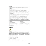
Page 11: ...ct and disconnect cables as described in the following table when installing moving or opening covers on this product or attached devices To Connect To Disconnect 1 Turn everything OFF 2 First attach all cables to devices 3 Attach signal cables to connectors 4 Attach power cords to outlet 5 Turn device ON 1 Turn everything OFF 2 First remove power cords from outlet 3 Remove signal cables from conn...

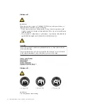
Page 12: ...res other than those specified herein might result in hazardous radiation exposure DANGER Some laser products contain an embedded Class 3A or Class 3B laser diode Note the following Laser radiation when open Do not stare into the beam do not view directly with optical instruments and avoid direct exposure to the beam Class 1 Laser Product Laser Klasse 1 Laser Klass 1 Luokan 1 Laserlaite Appareil A...

Page 13: ...voltage current and energy levels are present inside any component that has this label attached There are no serviceable parts inside these components If you suspect a problem with one of these parts contact a service technician Statement 12 CAUTION The following label indicates a hot surface nearby Statement 13 Safety xi ...

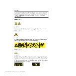
Page 14: ...over before installing the blade Statement 32 CAUTION To avoid personal injury before lifting the unit remove all the blades power supplies and removable modules to reduce the weight 108 kg 237 lbs 2X 6X 4X 4X 43 2 kg 95 lbs Statement 33 CAUTION This device does not provide a power control button Removing power supply modules or turning off the server blades does not turn off the electrical curren...

Page 15: ... install stabilizer brackets on the rack cabinet v Always install servers and optional devices starting from the bottom of the rack cabinet v Always install the heaviest devices in the bottom of the rack cabinet UL regulatory information This device is for use only with supported blade chassis Safety xiii ...

Page 16: ...xiv BladeCenter GPU Expansion Blade Installation Guide ...

Page 17: ...adeCenter units The expansion blade comes with a one year limited warranty For information about your warranty see the Warranty Information document for your device on the IBM Documentation CD You can obtain up to date information about the expansion blade and other IBM BladeCenter products at http www ibm com systems bladecenter If you participate in the IBM client reference program you can share...

Page 18: ...ation Browser to help you find information quickly Hardware and software requirements The IBM Documentation CD requires the following minimum hardware and software v Microsoft Windows XP Windows 2000 or Red Hat Linux v 100 MHz microprocessor v 32 MB of RAM v Adobe Acrobat Reader 3 0 or later or xpdf which comes with Linux operating systems Using the Documentation Browser Use the Documentation Brow...

Page 19: ... F to use the xpdf search function within the document Click Help for detailed information about using the Documentation Browser Notices and statements in this document The caution and danger statements that appear in this document are also in the multilingual Safety Information document which is on the IBM Documentation CD Each statement is numbered for reference to the corresponding statement in...

Page 20: ...4 BladeCenter GPU Expansion Blade Installation Guide ...

Page 21: ...ates that an error has occurred in the expansion blade The expansion blade error LED turns off only after the error is corrected If an error occurs in the expansion blade the fault LED on the blade device on which the expansion blade is installed is also lit Additional information about the error is provided by the light path LEDs in the expansion blade see Light path diagnostics on page 22 for ad...

Page 22: ...6 BladeCenter GPU Expansion Blade Installation Guide ...

Page 23: ...or additional information about tools for updating managing and deploying firmware see the System x and BladeCenter Tools Center at http publib boulder ibm com infocenter toolsctr v1r0 index jsp v Observe good housekeeping in the area where you are working Place removed covers and other parts in a safe place v Back up all important data before you make changes to disk drives v Before you remove a ...

Page 24: ... unit or any unpainted metal surface on any other grounded rack component in the rack in which you are installing the device for at least 2 seconds This drains static electricity from the package and from your body v Remove the device from its package and install it directly into the blade server without setting down the device If it is necessary to set down the device put it back into its static ...

Page 25: ...de on a blade server or an additional expansion blade on another expansion blade complete the following steps 1 Read the safety information that begins on Safety on page v and Installation guidelines on page 7 2 Shut down the operating system turn off the blade server and remove the blade server or combined blade server and expansion blades from the BladeCenter unit see the documentation that come...

Page 26: ... contains the expansion blade to any unpainted metal surface on the BladeCenter unit or any unpainted metal surface on any other grounded rack component in the rack in which you are installing the expansion blade for at least 2 seconds Then remove the expansion blade from the package Note Make sure that all devices are installed in the expansion blade before attaching it to the blade server see In...

Page 27: ...er bays b When a BladeCenter GPU Expansion Blade is installed on a blade device it cannot be combined with other expansion unit types c For complete instructions see the documents that came with your BladeCenter unit d See the documentation for your blade server and BladeCenter unit for additional device specific installation information 8 Up to three BladeCenter GPU Expansion Blades can be attach...

Page 28: ...r unit 11 Turn on the blade server see the documentation that comes with the blade server for more information 12 If you installed the blade server in a BladeCenter unit that has a bezel reinstall the bezel assembly see the documentation for your BladeCenter unit for instructions 12 BladeCenter GPU Expansion Blade Installation Guide ...

Page 29: ...installed in a BladeCenter unit shut down the operating system and turn off the blade server then remove the combined blade server and expansion blades from the BladeCenter unit see the documentation that comes with the blade server for more information 3 Carefully lay the combined unit down on a flat static protective surface with the cover side up 4 Press the cover release on each side of the bl...

Page 30: ...d in a BladeCenter unit shut down the operating system and turn off the blade server then remove the combined blade server and expansion blades from the BladeCenter unit see the documentation that comes with the blade server for more information 3 Carefully lay the combined unit down on a flat static protective surface with the cover side up 4 Press the cover release on each side of the expansion ...

Page 31: ...r Cover release Cover release To install the expansion blade cover complete the following steps 1 Read the Safety information beginning on page Safety on page v and Installation guidelines on page 7 2 Orient the cover over the expansion blade 3 Lower the cover so that the slots at the rear slide down onto the pins at the rear of the expansion blade 4 Pivot the cover closed and press it firmly into...

Page 32: ...r v The network interface type of the I O expansion card must be supported by the corresponding I O modules in the BladeCenter unit The high speed cards provide a connection to BladeCenter unit I O bays 7 through 10 if the BladeCenter unit has these I O module bays The following illustration shows how to install a CFFh expansion card To install a CFFh expansion card complete the following steps 1 ...

Page 33: ...es v Removing a GPU adapter v Installing a GPU adapter on page 19 Removing a GPU adapter Use this information to remove a GPU adapter from the expansion unit Note 1 The following illustration shows how to remove a GPU adapter from the expansion unit 2 The illustrations in this document might differ slightly from your hardware To remove a GPU adapter from the BladeCenter GPU expansion unit complete...

Page 34: ...ansion unit system board B c Locate the tray release button on the bottom of the expansion unit Tray release button d Press in and hold the tray release button then pull the expansion unit riser assembly out of the expansion unit system board 18 BladeCenter GPU Expansion Blade Installation Guide ...

Page 35: ...to remove the four non captive retaining screws as shown in the following illustration Store the screws in a safe location 6 Carefully turn the expansion unit riser assembly back over Unplug the GPU adapter from the PCI connector in the riser assembly and lift it out of the riser assembly ...

Page 36: ...xpansion blade cover on page 14 4 Touch the static protective package that contains the GPU adapter to any unpainted metal surface of the BladeCenter unit or any unpainted metal surface on any other grounded rack component for at least 2 seconds 5 Remove the GPU adapter from its static protective package 6 Connect the GPU adapter to the PCI connector in the expansion unit riser assembly as shown i...

Page 37: ...own in the illustration above 13 If you have other devices to install or remove do so now otherwise go to Completing the installation Completing the installation To complete the installation complete the following steps 1 Install any expansion blades that were removed and the expansion blade cover see Installing a GPU Expansion Blade on page 8 and Installing the expansion blade cover on page 15 2 ...

Page 38: ...d LED information fault related information will be shown by the BladeCenter advanced management module see the BladeCenter Advanced Management Module User s Guide for additional information If you cannot locate and correct a problem by using the information in this section see Getting help and technical assistance on page 27 for more information To view the light path LEDs 1 Remove the combined b...

Page 39: ...o the BladeCenter for 5 10 minutes to recharge the LEDs None An error has occurred and cannot be isolated An error has occurred with the GPU adapter 1 Make sure that the light path diagnostics LP LED is lit to ensure that there is enough power in the blade server to light the rest of the LEDs 2 Check the blade device and BladeCenter advanced management module event logs for information about an er...

Page 40: ...ector 4 Replace the expansion blade BPE4 An error has occurred in the expansion blade 1 Check for other specific error LEDs that are lit in the expansion blade 2 If no other error LEDs are lit replace the expansion blade Ck Next An error has occurred in an expansion blade installed below this expansion blade in the stack Remove this expansion blade and check for error LEDs that are lit in the expa...

Page 41: ...itional charge under the type of warranty service that is designated for your server v Field replaceable unit FRU FRUs must be installed only by trained service technicians For an updated parts listing on the web go to http www ibm com systems support Description CRU part number Tier 1 CRU part number Tier 2 FRU part number IBM BladeCenter GPU Expansion Blade 68Y7493 Top cover 68Y8691 NVIDIA 6 GB ...

Page 42: ...26 BladeCenter GPU Expansion Blade Installation Guide ...

Page 43: ...contract Your IBM service technician will request that you upgrade your software and firmware if the problem has a documented solution within a software upgrade v If you have installed new hardware or software in your environment check http www ibm com systems info x86servers serverproven compat us to make sure that the hardware and software is supported by your IBM product v Go to http www ibm co...

Page 44: ...tp www ibm com supportportal Getting help and information from the World Wide Web Up to date information about IBM products and support is available on the World Wide Web On the World Wide Web up to date information about IBM systems optional devices services and support is available at http www ibm com supportportal IBM System x information is at http www ibm com systems x IBM BladeCenter informa...

Page 45: ...426 7378 Hardware service and support You can receive hardware service through your IBM reseller or IBM Services To locate a reseller authorized by IBM to provide warranty service go to http www ibm com partnerworld and click Find Business Partners on the right side of the page For IBM support telephone numbers see http www ibm com planetwide In the U S and Canada call 1 800 IBM SERV 1 800 426 737...

Page 46: ...30 BladeCenter GPU Expansion Blade Installation Guide ...

Page 47: ...HE IMPLIED WARRANTIES OF NON INFRINGEMENT MERCHANTABILITY OR FITNESS FOR A PARTICULAR PURPOSE Some states do not allow disclaimer of express or implied warranties in certain transactions therefore this statement may not apply to you This information could include technical inaccuracies or typographical errors Changes are periodically made to the information herein these changes will be incorporate...

Page 48: ...e maximum When referring to processor storage real and virtual storage or channel volume KB stands for 1024 bytes MB stands for 1 048 576 bytes and GB stands for 1 073 741 824 bytes When referring to hard disk drive capacity or communications volume MB stands for 1 000 000 bytes and GB stands for 1 000 000 000 bytes Total user accessible capacity can vary depending on operating environments Maximu...

Page 49: ... 1 Limits for particulates and gases Contaminant Limits Particulate v The room air must be continuously filtered with 40 atmospheric dust spot efficiency MERV 9 according to ASHRAE Standard 52 21 v Air that enters a data center must be filtered to 99 97 efficiency or greater using high efficiency particulate air HEPA filters that meet MIL STD 282 v The deliquescent relative humidity of the particu...

Page 50: ...t generates uses and can radiate radio frequency energy and if not installed and used in accordance with the instruction manual may cause harmful interference to radio communications Operation of this equipment in a residential area is likely to cause harmful interference in which case the user will be required to correct the interference at his own expense Properly shielded and grounded cables an...

Page 51: ...tions Department M372 IBM Allee 1 71139 Ehningen Germany Telephone 49 7032 15 2941 Email lugi de ibm com Germany Class A statement Deutschsprachiger EU Hinweis Hinweis für Geräte der Klasse A EU Richtlinie zur Elektromagnetischen Verträglichkeit Dieses Produkt entspricht den Schutzanforderungen der EU Richtlinie 2004 108 EG zur Angleichung der Rechtsvorschriften über die elektromagnetische Verträg...

Page 52: ...Hersteller International Business Machines Corp New Orchard Road Armonk New York 10504 914 499 1900 Der verantwortliche Ansprechpartner des Herstellers in der EU ist IBM Deutschland GmbH Technical Regulations Abteilung M372 IBM Allee 1 71139 Ehningen Germany Telephone 49 7032 15 2941 Email lugi de ibm com Generelle Informationen Das Gerät erfüllt die Schutzanforderungen nach EN 55024 und EN 55022 ...

Page 53: ... Communications Commission KCC statement This is electromagnetic wave compatibility equipment for business Type A Sellers and users need to pay attention to it This is for any areas other than home Russia Electromagnetic Interference EMI Class A statement People s Republic of China Class A electronic emission statement Taiwan Class A compliance statement Notices 37 ...

Page 54: ...38 BladeCenter GPU Expansion Blade Installation Guide ...

Page 55: ...ervice 29 important notices 32 Industry Canada Class A emission compliance statement 34 information center 28 inspecting for unsafe conditions vi Install 8 installation procedure 20 installing CFFh expansion card 16 GPU adapter 20 guidelines 7 I O expansion card 16 installing the cover expansion blade 15 J Japan Electronics and Information Technology Industries Association statement 36 Japan VCCI ...

Page 56: ...s electronic emission Class A notice 34 United States FCC Class A notice 34 unsafe conditions inspecting for vi W warranty 1 website compatible optional devices 7 40 BladeCenter GPU Expansion Blade Installation Guide ...

Page 57: ......

Page 58: ... Part Number 90Y5467 Printed in USA 1P P N 90Y5467 ...

Reviews: