


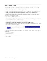


The following figure shows the configuration of Type 6 PDUs.
L1
CB1
CB2
CB3
CB4
CB5
CB6
R6
R5
R4
R3
R2
R1
Outlet for Drawers
Reset Buttons
Power Cord
(Plug Configuration
May Vary)
CB8
CB7
R7
R8
View of Power
Distribution Unit
Facing Front of Rack
Outlets for
Peripherals
(Two Facing
Front of Rack)
Reset Buttons
(Two Facing
Front of Rack )
Type 6 Power Distribution Unit
View of Power
Distribution Unit
Facing Rear of Rack
342
Site and Hardware Planning Information
Summary of Contents for 7012 397
Page 1: ...RS 6000 and Eserver pSeries Site and Hardware Planning Information SA38 0508 20...
Page 2: ......
Page 3: ...RS 6000 and Eserver pSeries Site and Hardware Planning Information SA38 0508 20...
Page 11: ...Appendix Notices 385 Index 387 Contents ix...
Page 12: ...x Site and Hardware Planning Information...
Page 16: ...xiv Site and Hardware Planning Information...
Page 18: ...xvi Site and Hardware Planning Information...
Page 26: ...8 Site and Hardware Planning Information...
Page 238: ...220 Site and Hardware Planning Information...
Page 246: ...228 Site and Hardware Planning Information...
Page 284: ...266 Site and Hardware Planning Information...
Page 296: ...278 Site and Hardware Planning Information...
Page 366: ...348 Site and Hardware Planning Information...
Page 372: ...Async Adapter Cable Planning Chart 354 Site and Hardware Planning Information...
Page 377: ...Standard I O Cable Planning Chart Chapter 12 Cable Planning 359...
Page 380: ...Cable Planning Chart Other Adapters 362 Site and Hardware Planning Information...
Page 384: ...366 Site and Hardware Planning Information...
Page 402: ...384 Site and Hardware Planning Information...
Page 404: ...386 Site and Hardware Planning Information...
Page 413: ......
Page 414: ...Printed in USA SA38 0508 20...
Page 415: ...Spine information RS 6000 and Eserver pSeries Site and Hardware Planning Information...


