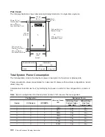


5. Remove the pin and the spacer from the lower jaw (see the following illustrations).
1
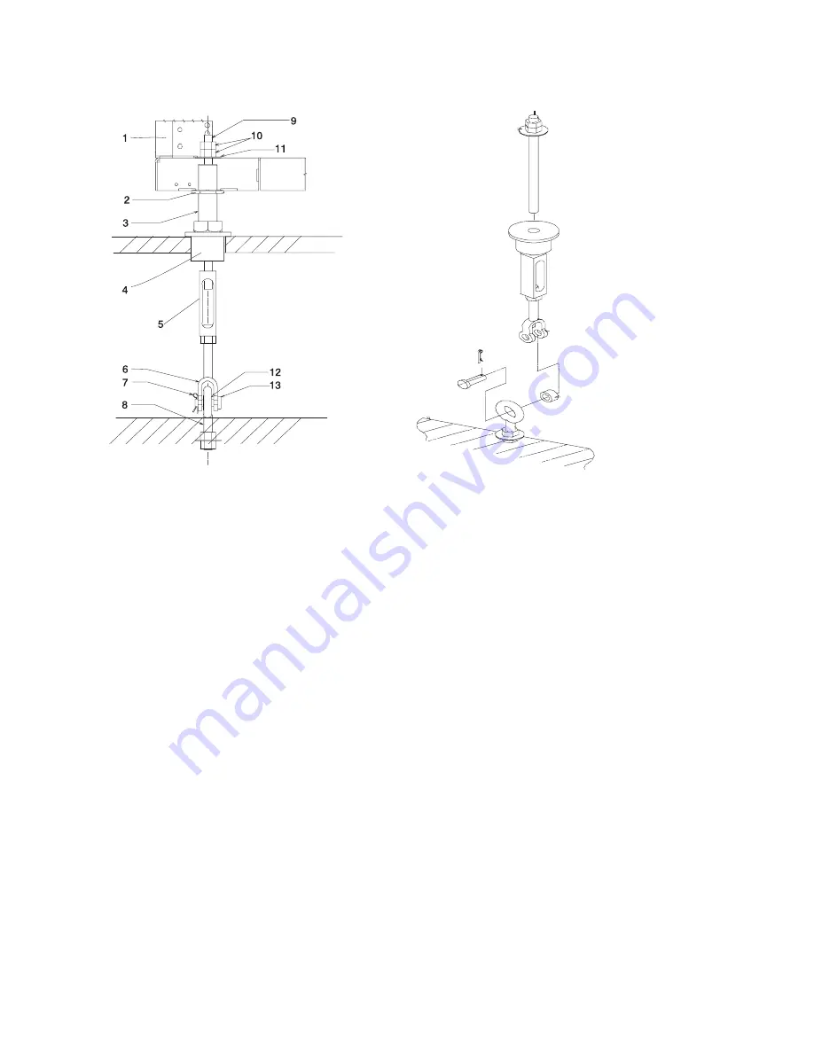
Frame
8
Floor Eyebolt (customer-supplied)
2
Jam Nut
9
Threaded Rod
3
Rack Leveler
10
Nut
4
Rubber Bushing
11
Washer
5
Turnbuckle (Short or Long)
12
Spacer
6
Lower Jaw
13
Shaft
7
Pin
Note:
The difference between the two turnbuckle assemblies is the length of the turnbuckle.
The Short Turnbuckle Assembly (part number 11P4755) is used for a 9 1/2 inches to 11 3/4
inches raised floor.
The Long Turnbuckle Assembly (part number 11P4756) is used for an 11 3/4 inches to 16
inches raised floor.
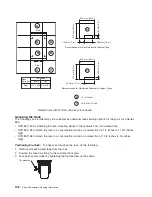
6.
Place the spacer inside the floor eyebolt and place the floor eyebolt between the lower jaw. Reinstall
the shaft, pin, and spacer.
7.
Remove the threaded rod and rubber bushing from the turnbuckle assembly.
8.
Install the floor tile that has the rubber bushing holes that are aligned with the eyebolt locations.
9.
Install the rubber bushings in the floor tiles.
10. Move the frame so that the frame leveler is located over the rubber bushings.
Attention:
To avoid a tipping hazard, make sure that the frame casters do not roll into the cable
opening.
11. Turn the leveling foot of the plate assembly down until it contacts the bushing, and then level the rack
using the four leveling feet by tightening the lock nuts.
12. Lock the leveling feet by tightening the lock nut.
13. Insert the threaded rod into the inner hole of the leveler and the rubber bushing.
114
Site and Hardware Planning Information
Summary of Contents for 7012 397
Page 1: ...RS 6000 and Eserver pSeries Site and Hardware Planning Information SA38 0508 20...
Page 2: ......
Page 3: ...RS 6000 and Eserver pSeries Site and Hardware Planning Information SA38 0508 20...
Page 11: ...Appendix Notices 385 Index 387 Contents ix...
Page 12: ...x Site and Hardware Planning Information...
Page 16: ...xiv Site and Hardware Planning Information...
Page 18: ...xvi Site and Hardware Planning Information...
Page 26: ...8 Site and Hardware Planning Information...
Page 238: ...220 Site and Hardware Planning Information...
Page 246: ...228 Site and Hardware Planning Information...
Page 284: ...266 Site and Hardware Planning Information...
Page 296: ...278 Site and Hardware Planning Information...
Page 366: ...348 Site and Hardware Planning Information...
Page 372: ...Async Adapter Cable Planning Chart 354 Site and Hardware Planning Information...
Page 377: ...Standard I O Cable Planning Chart Chapter 12 Cable Planning 359...
Page 380: ...Cable Planning Chart Other Adapters 362 Site and Hardware Planning Information...
Page 384: ...366 Site and Hardware Planning Information...
Page 402: ...384 Site and Hardware Planning Information...
Page 404: ...386 Site and Hardware Planning Information...
Page 413: ......
Page 414: ...Printed in USA SA38 0508 20...
Page 415: ...Spine information RS 6000 and Eserver pSeries Site and Hardware Planning Information...


