4.
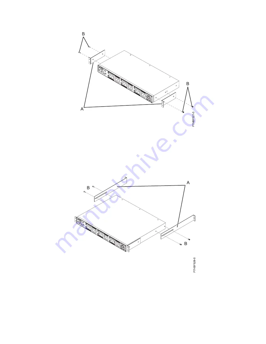
Attach the brackets
(A)
to the PDU+ with two M3x5 screws
(B)
per bracket. Use screws that were
provided with the rack mounting kit.
5.
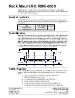
Align the long mounting brackets
(A)
with the holes in the rear of the PDU model, and attach the
brackets to the PDU model with two M3 pan-head screws
(B)
with captive lock washers per bracket.
Use screws that were provided with the rack mounting kit.
6.
Identify an open mounting space that is the size of a single EIA in the rack where you will install
the PDU model. At the front of the rack, attach an M6 screw to the middle hole of the EIA on each
side of the rack. At the rear of the rack, attach nut clips to the top and bottom holes of the EIA on
each side of the rack. Use nut clips that were provided with the rack mounting kit.
Figure 42. Aligning the vertical-mounting brackets to the front of the PDU+
Figure 43. Attaching the long mounting brackets
Racks and rack features
43
Summary of Contents for 7014-T42
Page 1: ...Power Systems Racks and rack features ...
Page 2: ......
Page 3: ...Power Systems Racks and rack features ...
Page 6: ...iv Power Systems Racks and rack features ...
Page 72: ...60 Power Systems Racks and rack features ...
Page 73: ......
Page 74: ... Printed in USA ...


