


4-54
Service Guide
If the CPU module does NOT have a docking screw retention bracket, perform the
next step.
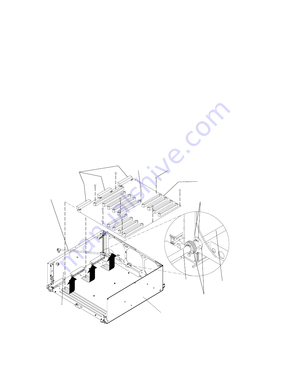
6. For earlier versions of the CPU module, remove the docking screw by removing the two
retainer clips and the three washers, and then remove the docking screw.
Go to step 7.
7. Remove the flex cable restraint bracket retainer screw and the flex cable restraint
bracket from the CPU module.
8. Remove the nine mounting screws (R50 uses 12 screws) attaching the system planar to
the CPU module.
9. Grasp the system planar near the three power interface connectors, and then pull the
system planar away from the lateral planar 1 card until the system planar disconnects
from the lateral planar 1 card; immediately lift the system planar out of the CPU module.
Attention: As soon as the system planar is disconnected from the lateral planar 1 card, lift
the planar upward to avoid sliding the bottom of the system planar on the CPU module.
Sliding the bottom of the system planar on the CPU module can damage the soldered
connectors on the bottom of the system planar.
Lateral
Planar 1
Card
Mounting Screw
(1 pan head)
System
Planar
CPU
Module
Power
Interface
Connectors
Docking
Screw
2 Inside Washers 1
Outside Washer
Clips
Docking
Screw
Docking
Screw
Mounting Screws
(8 on R30, R40
11 on R50 )
Summary of Contents for 7015-R30
Page 1: ...7015 Models R30 R40 and R50 CPU Enclosure Installation and Service Guide...
Page 10: ...x Service Guide...
Page 14: ...xiv Service Guide...
Page 34: ...1 20 Service Guide...
Page 214: ...6 10 Service Guide Detail 5 CPU Module 2 of 3 26 27 29 30 31 32 33 34 28 35...
Page 216: ...6 12 Service Guide Detail 6 CPU Module 3 of 3 36 37...
Page 252: ...B 8 Installation and Service Guide...
Page 288: ...Service Guide D 30...
Page 299: ......


