1-4
Service Guide
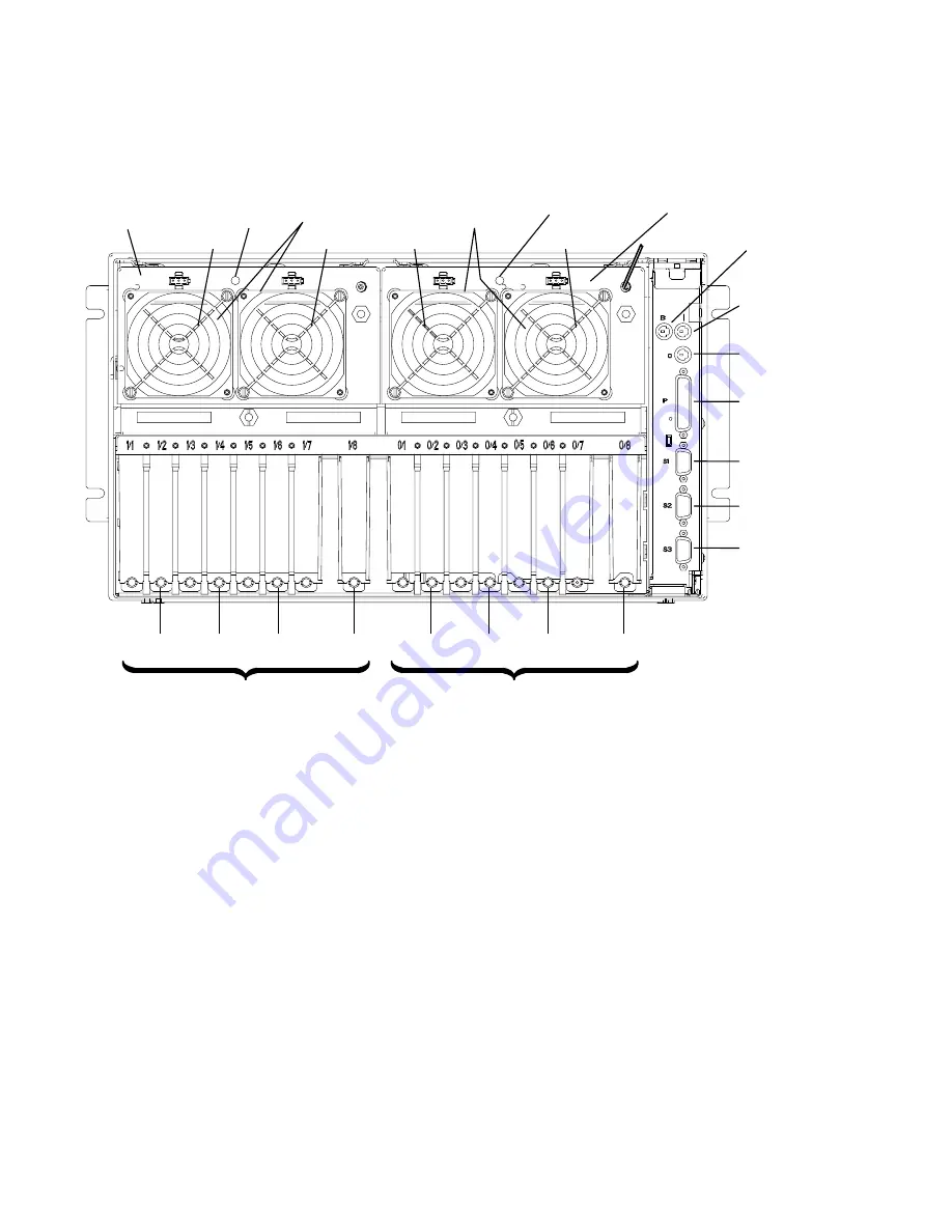
Rear Connector Locations with Rear Access Plate Removed
Power Supply
Cooling Unit or 2nd
Power Supply Fans
Power
Supply
Fans
Parallel
Port
Serial
Port 1
Serial
Port 2
Adapter Locations
Adapter Locations
Serial
Port 3
RS485 (Out)
Battery
Backup Unit
Connector
RS485 (In)
0/1
1/1
0/2
0/3
0/4
0/5
0/6
0/7
0/8
1/2
1/3
1/4
1/5
1/6
1/7
1/8
Cooling Unit or
2nd Power Supply
Power
Light
Power
Light
Fan 4
Fan 3
Fan 2
Fan 1
Note: Fans 3 and 4 above are in reversed positions if a cooling unit is installed instead of
an optional power supply.
Serial Ports
Serial Ports 1 and 2 are reserved for maintenance purposes. Serial Port 3 is used to
manage an optional external uninterruptible power supply (UPS). Serial Ports 1, 2 and 3 can
also be used as async terminal lines.
Summary of Contents for 7015-R30
Page 1: ...7015 Models R30 R40 and R50 CPU Enclosure Installation and Service Guide...
Page 10: ...x Service Guide...
Page 14: ...xiv Service Guide...
Page 34: ...1 20 Service Guide...
Page 214: ...6 10 Service Guide Detail 5 CPU Module 2 of 3 26 27 29 30 31 32 33 34 28 35...
Page 216: ...6 12 Service Guide Detail 6 CPU Module 3 of 3 36 37...
Page 252: ...B 8 Installation and Service Guide...
Page 288: ...Service Guide D 30...
Page 299: ......


