4-12
Service Guide
Note: For a translation of this notice, see the
System Unit Safety Information manual.
DANGER
An electrical outlet that is not correctly wired could place hazardous voltage
on metal parts of the system or the devices that attach to the system. It is the
responsibility of the customer to ensure that the outlet is correctly wired and
grounded to prevent an electrical shock.
Before installing or removing any additional devices to or from the system,
ensure that the power cables for those devices are unplugged before the signal
cables are connected. If possible, disconnect all power cables from the existing
system before you add a device.
Use one hand, when possible, to connect or disconnect signal cables to prevent a
possible shock from touching two surfaces with different electrical potentials.
During an electrical storm, do not connect cables for display stations, printers,
telephones, or station protectors, for communications lines.
CAUTION:
Energy hazard, remove power before servicing. Disconnect two power supply cords.
2. Remove the six mounting screws attaching the top cover to the PDP, and then remove
the top cover.
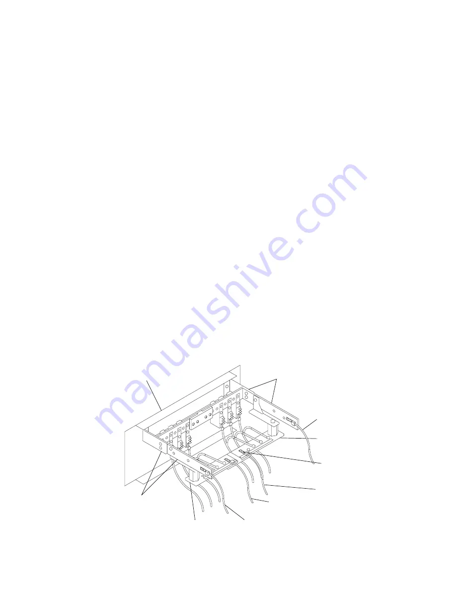
3. Ensure that the four power cables (-48 V dc ( – ) and return (+)) from each -48 V dc
power source are connected to the power distribution panel.
4. Use a multimeter to ensure that -48 V dc power is entering the rack on both A & B side.
Notes:
1. An electrical hazard from an external -48 V dc power source exists in this unit. To
prevent electrical shock, ensure that power to this unit is off before servicing.
2. The customer is responsible for providing and connecting power cables from the
customer’s -48 V dc power source to the power distribution panel.
Front of Power
Distribution Panel
A -48 V dc ( – )
Bus Bar
A-48 V dc ( – )
Power Cable
A Return (+)
Bus Bar
A Return (+)
Power Cable
B Return (+)
Bus Bar
B-48 V dc ( – )
Power Cable
B Return (+)
Power Cable
B -48 V dc ( – )
Bus Bar
10mm hole,
25.4mm spacing
Summary of Contents for 7015-R50
Page 1: ...7015 Models R30 R40 and R50 CPU Enclosure Installation and Service Guide...
Page 10: ...x Service Guide...
Page 14: ...xiv Service Guide...
Page 34: ...1 20 Service Guide...
Page 214: ...6 10 Service Guide Detail 5 CPU Module 2 of 3 26 27 29 30 31 32 33 34 28 35...
Page 216: ...6 12 Service Guide Detail 6 CPU Module 3 of 3 36 37...
Page 252: ...B 8 Installation and Service Guide...
Page 288: ...Service Guide D 30...
Page 299: ......


