Service Guide
4-26
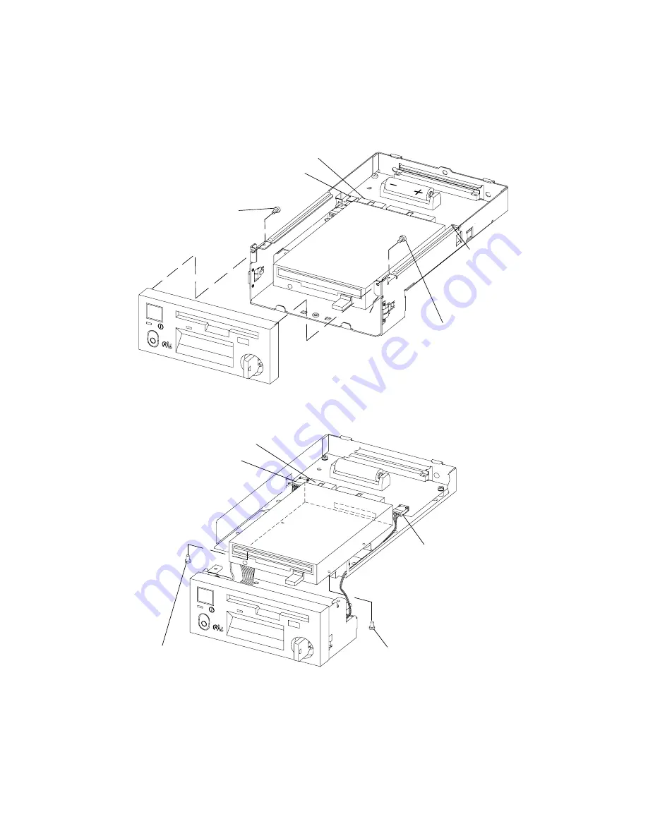
4. Disconnect the two power connectors and the data connector.
5. For later models, remove the two mounting screws attaching the bezel to the operator
panel assembly at the top corners of the operator panel assembly, and then remove the
bezel.
Bezel Mounting
Screw
Bezel Mounting
Screw
Power Connector
Data Connector
Power
Connector
6. For earlier models, remove the two mounting screws attaching the bezel to the bottom of
the operator panel assembly, and then remove the bezel.
Mounting Screw
Attaching Bezel
Mounting Screw
Attaching Bezel
Power Connector
Data Connector
Power
Connector
Replacement
Replace in the reverse order of the removal procedure.
Summary of Contents for 7015-R50
Page 1: ...7015 Models R30 R40 and R50 CPU Enclosure Installation and Service Guide...
Page 10: ...x Service Guide...
Page 14: ...xiv Service Guide...
Page 34: ...1 20 Service Guide...
Page 214: ...6 10 Service Guide Detail 5 CPU Module 2 of 3 26 27 29 30 31 32 33 34 28 35...
Page 216: ...6 12 Service Guide Detail 6 CPU Module 3 of 3 36 37...
Page 252: ...B 8 Installation and Service Guide...
Page 288: ...Service Guide D 30...
Page 299: ......


