4-40
Service Guide
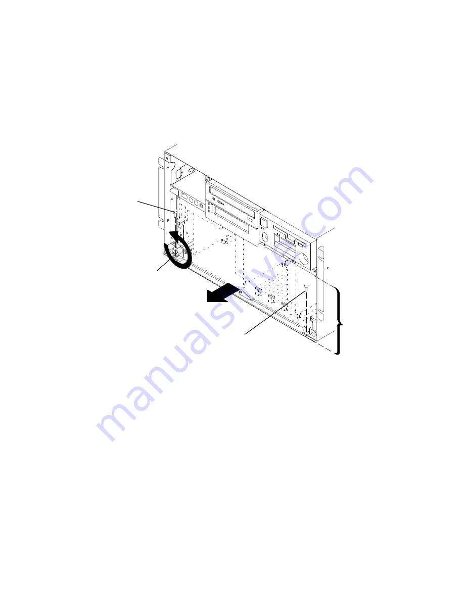
3. Remove the two retainer screws.
4. Loosen the docking screw until the CPU module is disengaged from the I/O planar
interface connectors.
5. Grasp the front of the CPU module, and then pull the CPU module toward you until you
can grasp the bottom of the CPU module on each side.
Front View of CPU Enclosure
Retainer Screw
Docking Screw
Retainer
Screw
CPU
Module
Summary of Contents for 7015-R50
Page 1: ...7015 Models R30 R40 and R50 CPU Enclosure Installation and Service Guide...
Page 10: ...x Service Guide...
Page 14: ...xiv Service Guide...
Page 34: ...1 20 Service Guide...
Page 214: ...6 10 Service Guide Detail 5 CPU Module 2 of 3 26 27 29 30 31 32 33 34 28 35...
Page 216: ...6 12 Service Guide Detail 6 CPU Module 3 of 3 36 37...
Page 252: ...B 8 Installation and Service Guide...
Page 288: ...Service Guide D 30...
Page 299: ......


