Removal and Replacement
4-47
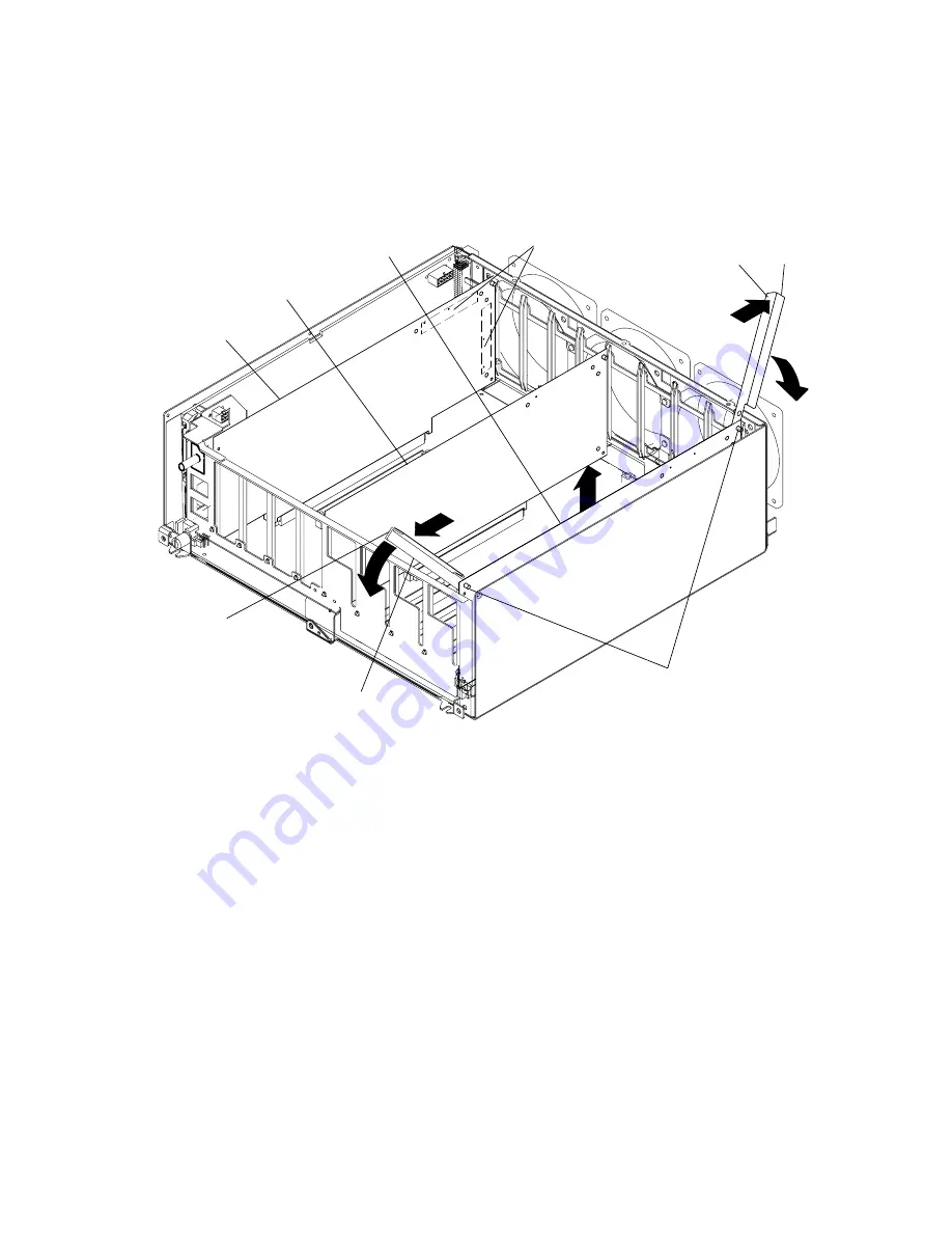
– R50 CPU Enclosure: Position single-piece extraction tools on either end of the card
you are removing by placing the pin of the extraction tool through the hole in the top
corner of the card you are removing.
Single-Piece
Extraction Tool
Single-Piece
Extraction
Tool
Pins of
Extraction
Tools
Handle
Handle
CPU
Card
I/O
Card
Memory
Card
Flex Cable Connectors
(on back of card)
5. With both extraction tools positioned on the card, firmly rotate both handles of the
extraction tools downward until the card disengages from the slot, and then remove the
card.
6. If you are removing a single in-line memory module from a memory card, refer to the
“Memory module” removal and replacement procedure on page 4-49
.
Summary of Contents for 7015-R50
Page 1: ...7015 Models R30 R40 and R50 CPU Enclosure Installation and Service Guide...
Page 10: ...x Service Guide...
Page 14: ...xiv Service Guide...
Page 34: ...1 20 Service Guide...
Page 214: ...6 10 Service Guide Detail 5 CPU Module 2 of 3 26 27 29 30 31 32 33 34 28 35...
Page 216: ...6 12 Service Guide Detail 6 CPU Module 3 of 3 36 37...
Page 252: ...B 8 Installation and Service Guide...
Page 288: ...Service Guide D 30...
Page 299: ......


