Removal and Replacement
4-57
CPU Module Flex Cables
Removal
1. Do the “CPU Module” removal procedure on page 4-39.
2. Remove the I/O card and all of the CPU cards. Refer to the “Memory Card, CPU Card,
or I/O Card” removal procedure on page 4-45 to remove the I/O card and all of the CPU
cards.
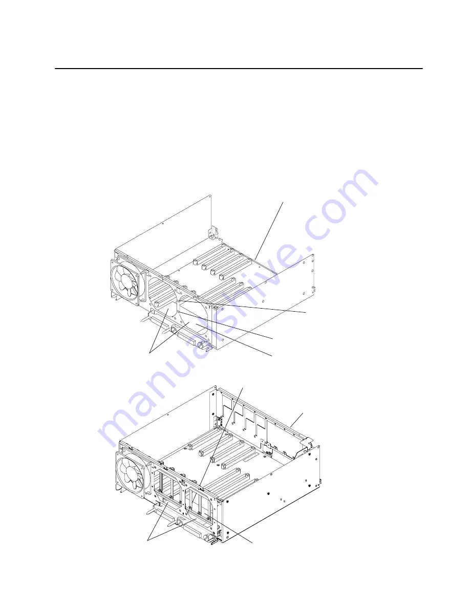
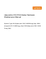
3. Remove the mounting screw on the flex cable retainer bracket.
4. Rotate the retainer bracket upwards until you can pull the retainer bracket out of the
retainer bracket tab opening, and then remove the retainer bracket.
CPU Module
Mounting Screw
Bracket Tab
Opening
Flex Cable
Retainer Bracket
Two Fans Are Shown Removed to Show
the Flex Cable Retainer Bracket
R30, R40
CPU
Module
Mounting Screw (Access
from inside CPU Module)
Flex Cable
Retainer Bracket
Two Fans Are Shown Removed
to Show The Flex Cable Bracket
R50
Summary of Contents for 7015-R50
Page 1: ...7015 Models R30 R40 and R50 CPU Enclosure Installation and Service Guide...
Page 10: ...x Service Guide...
Page 14: ...xiv Service Guide...
Page 34: ...1 20 Service Guide...
Page 214: ...6 10 Service Guide Detail 5 CPU Module 2 of 3 26 27 29 30 31 32 33 34 28 35...
Page 216: ...6 12 Service Guide Detail 6 CPU Module 3 of 3 36 37...
Page 252: ...B 8 Installation and Service Guide...
Page 288: ...Service Guide D 30...
Page 299: ......


