4-60
Service Guide
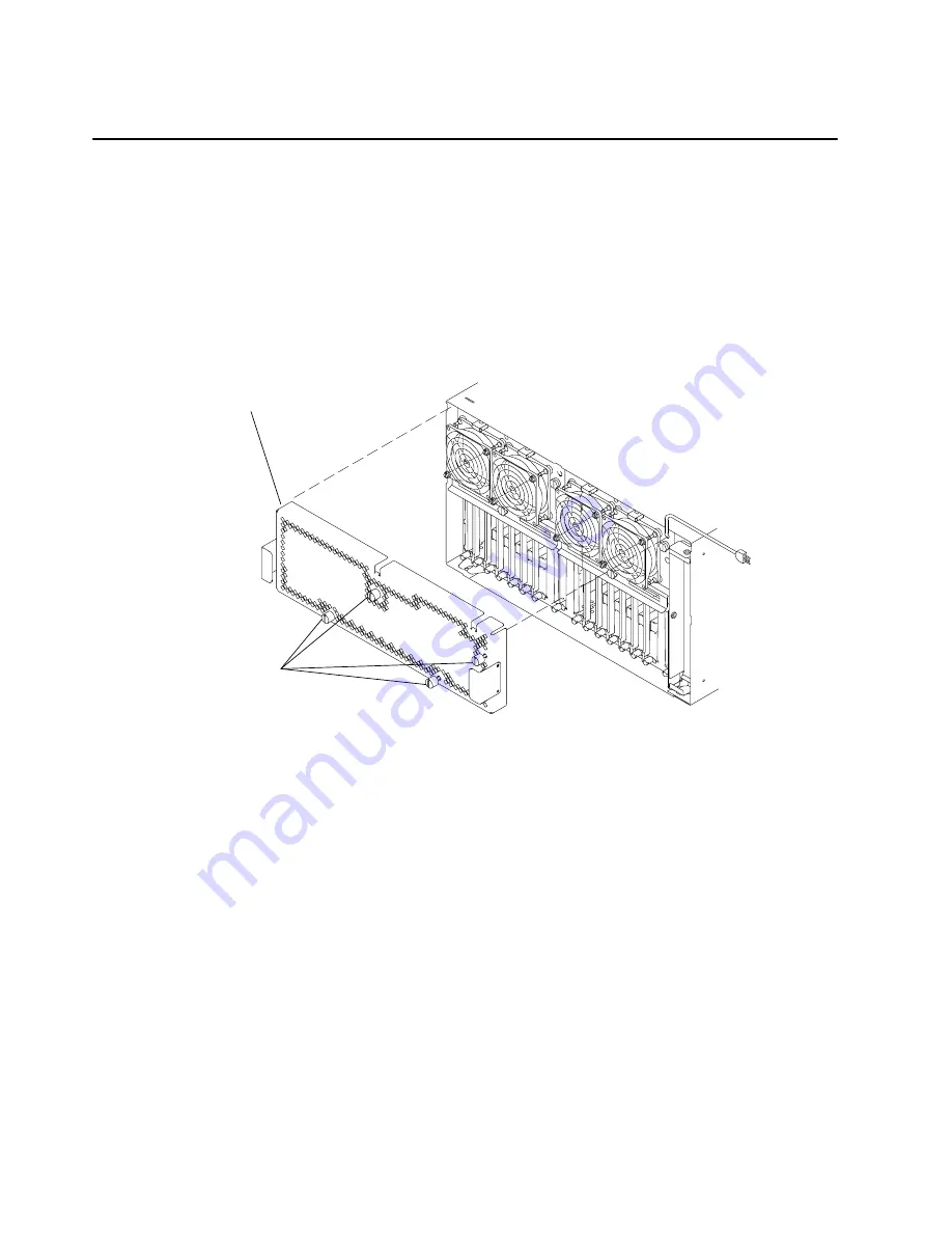
Rear Access Plate
Removal
1. Depending on the power distribution in your rack, do one of the following:
•
“Power-Off Procedure with a Power Distribution Bus” on page 4-2.
•
“Power-Off Procedure with a Power Distribution Unit” on page 4-5.
•
“Power-Off Procedure with a Power Distribution Panel” on page 4-9.
2. Loosen the four retainer screws until the screws disengage from the CPU enclosure, and
then pull the rear access plate away from the CPU enclosure.
Retainer
Screws
(captured or
loose screws)
Rear Access Plate
Replacement
Notes:
1. Ensure that the grounding strips located around the edges of the rear access
plate are firmly attached and in place before replacing the rear access plate.
2. Do not over tighten the four retainer screws on the rear access plate.
1. Replace in the reverse order.
2. Depending on the power distribution in your rack, do one of the following Power-On
procedures:
•
“Power-On Procedure with a Power Distribution Bus” on page 4-4.
•
“Power-On Procedure with a Power Distribution Unit” on page 4-7.
•
“Power-On Procedure with a Power Distribution Panel” on page 4-11.
Summary of Contents for 7015-R50
Page 1: ...7015 Models R30 R40 and R50 CPU Enclosure Installation and Service Guide...
Page 10: ...x Service Guide...
Page 14: ...xiv Service Guide...
Page 34: ...1 20 Service Guide...
Page 214: ...6 10 Service Guide Detail 5 CPU Module 2 of 3 26 27 29 30 31 32 33 34 28 35...
Page 216: ...6 12 Service Guide Detail 6 CPU Module 3 of 3 36 37...
Page 252: ...B 8 Installation and Service Guide...
Page 288: ...Service Guide D 30...
Page 299: ......


