Removal and Replacement
4-77
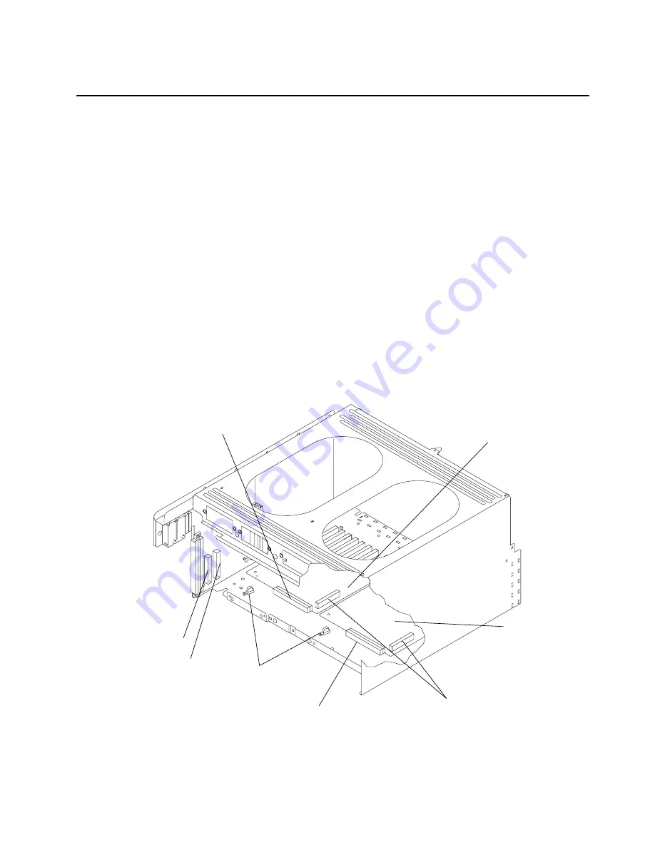
I/O Planar Power Cables
Removal
1. Perform the “I/O Module” removal procedure on page 4-67.
2. If any adapters are located over the I/O planar power cables, do the “Adapter” removal
procedure on page 4-75 to remove the adapters.
Attention: To prevent damage to the flex cables it is important to remove the I/O Module
Flex Cables before removing or replacing the I/O planar power cables.
3. To access the connectors for the I/O planar power cables, perform the “I/0 Module Flex
Cables” removal procedure on page 4-76.
4. Remove the mounting nut on each of the cable retainer.
Note: If you are removing both power cables, record the location of the connectors and
note how the cables are positioned.
5. Remove the shipping tape from the top of the I/O planar power cable you are removing.
6. Disconnect the I/O planar power cable connector on the I/O planar.
7. Depending on the I/O planar power cable connector you are removing, disconnect either
P13 or P14 on the lateral planar 2 card, and then remove the I/O planar power cable.
P13
Flex Cable
Connectors
I/O Planar 2
P14
I/O Planar Power Cable
Connector
I/O Planar 1
I/O Planar Power Cable
Connector
Cable
Retainers
Replacement
Replace in the reverse order.
Summary of Contents for 7015-R50
Page 1: ...7015 Models R30 R40 and R50 CPU Enclosure Installation and Service Guide...
Page 10: ...x Service Guide...
Page 14: ...xiv Service Guide...
Page 34: ...1 20 Service Guide...
Page 214: ...6 10 Service Guide Detail 5 CPU Module 2 of 3 26 27 29 30 31 32 33 34 28 35...
Page 216: ...6 12 Service Guide Detail 6 CPU Module 3 of 3 36 37...
Page 252: ...B 8 Installation and Service Guide...
Page 288: ...Service Guide D 30...
Page 299: ......


