Removal and Replacement
4-79
Power Distribution Cables
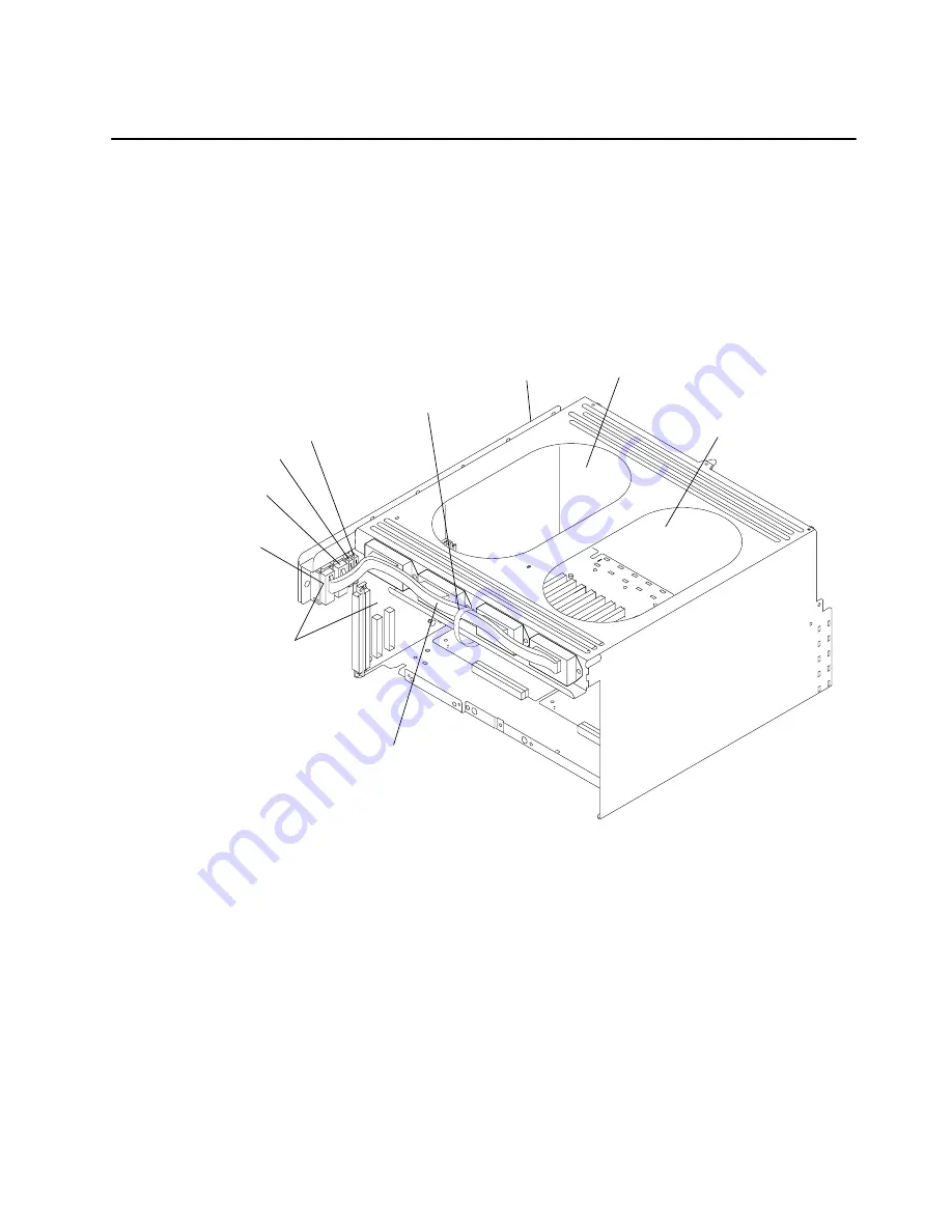
Removal
1. Perform the “Power Supply or Cooling Unit” removal procedure on page 4-61 to remove
the power supply and either the cooling unit or optional power supply.
2. Perform the “I/O Module” removal procedure on page 4-67.
3. Carefully cut the cable restraint straps for the power distribution cable.
4. Disconnect connectors P10, P11, P12, and P12A located on the lateral planar 2 card.
I/O Module
Lateral
Planar 2
Card
P10
P11
P12
Power Distribution
Cable
Cable
Restraint
Strap
Primary Power
Supply Location
Cooling Unit or
Optional Power
Supply Location
P12A
Summary of Contents for 7015-R50
Page 1: ...7015 Models R30 R40 and R50 CPU Enclosure Installation and Service Guide...
Page 10: ...x Service Guide...
Page 14: ...xiv Service Guide...
Page 34: ...1 20 Service Guide...
Page 214: ...6 10 Service Guide Detail 5 CPU Module 2 of 3 26 27 29 30 31 32 33 34 28 35...
Page 216: ...6 12 Service Guide Detail 6 CPU Module 3 of 3 36 37...
Page 252: ...B 8 Installation and Service Guide...
Page 288: ...Service Guide D 30...
Page 299: ......


