Using SystemGuard
2-3
The Operator Panel
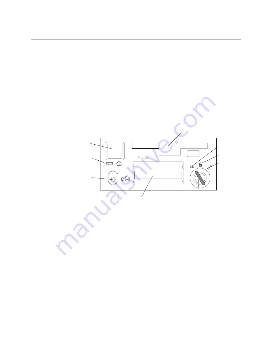
The Operator Panel is the first level of user interface to SystemGuard.
The Operator Panel has the following features:
Power button It should generally stay pushed in all the time if you want to be able to
power on or off the system remotely.
Reset button
It resets SystemGuard to the Init phase and, depending on the key position,
reboots the system to Maintenance or to AIX Multi-User.
LCD display
It is made of two rows of sixteen characters. It displays the word
Stand-By
in the Stand-By phase, or it displays the usual three-digit boot up codes.
Physical Key
It uses the international symbols for Normal, Secure and Service modes.
This key should generally stay in the Normal position because the modes
can be changed electronically when the physical key is in the Normal
position.
Operator Panel Display
Reset/Scroll
Button
Key Mode Switch
(Physical Key)
Power Light
Power Button
Diskette Drive
Normal
Secure
Service
In the 7015 R30, R40, and R50 CPU Enclosures the I/O card contains the NVRAM while the
NVRAM battery and the TOD (Time-Of-Day) are located in the Operator Panel. You can
drain NVRAM in the following ways:
removing the I/O card
disconnecting the operator panel
removing the CPU module.
When NVRAM is drained it results in a reset of the TOD to 1969 which affects applications.
Draining NVRAM also causes a loss of configuration data.
Summary of Contents for 7015-R50
Page 1: ...7015 Models R30 R40 and R50 CPU Enclosure Installation and Service Guide...
Page 10: ...x Service Guide...
Page 14: ...xiv Service Guide...
Page 34: ...1 20 Service Guide...
Page 214: ...6 10 Service Guide Detail 5 CPU Module 2 of 3 26 27 29 30 31 32 33 34 28 35...
Page 216: ...6 12 Service Guide Detail 6 CPU Module 3 of 3 36 37...
Page 252: ...B 8 Installation and Service Guide...
Page 288: ...Service Guide D 30...
Page 299: ......


