|
1
Refer to the Installation and Service Guide for the rack, and follow the instructions
|
given in “Power-Off Procedure with Power Distribution Panel.”
|
2
At the customer’s
−
48 volt dc power source, turn off the power from the
−
48 volt dc
|
power sources (A and B) to the power distribution panel.
|
Immediately the customer’s
−
48 V dc power source is turned off, ensure that a tag
|
or label is put over the switch to show that the power source must remain turned off.
|
Note: The remainder of this section describes the general procedure for removing the
|
power cable from the rack. For more details, refer to the Installation and Service Guide
|
for the rack.
|
3
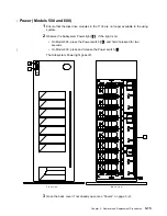
Remove the six screws
1
from the top cover
2
of the power distribution panel,
|
then remove the top cover.
|
4
Refer to the diagram on page 3-14. With a multimeter, verify that no power exists
|
between:
|
The B
−
48 volt dc bus bar
3
and the B return bar
7
|
The A
−
48 bus bar
4
and the A return bar
5
.
Chapter 3. Removal and Replacement Procedures
3-13
Summary of Contents for 7133 Series
Page 1: ...7133 SSA Disk Subsystems Service Guide SY33 0185 02...
Page 2: ......
Page 3: ...7133 SSA Disk Subsystems Service Guide SY33 0185 02...
Page 8: ...vi 7133 Service Guide...
Page 14: ...xii 7133 Service Guide...
Page 44: ...Labels Dummy Fan and Power Supply Assembly 1 30 7133 Service Guide...
Page 94: ...2 10 7133 Service Guide...
Page 110: ...2 2021 6 7133 Service Guide...
Page 114: ...2 2022 4 7133 Service Guide...
Page 138: ...2 2330 18 7133 Service Guide...
Page 146: ...2 16 7133 Service Guide...
Page 210: ...3 64 7133 Service Guide...
Page 222: ...4 12 7133 Service Guide...
Page 229: ......
Page 230: ...Part Number 32H6990 Printed in the United Kingdom 32H699 SY33 185 2...


