|
SSA Loops and Links
|
The disk drive modules of the 7133 are connected through two or more SSA links to an
|
SSA adapter that is located in the using system. The disk drive modules, SSA links, and
|
SSA adapter are configured in loops. Each loop provides a data path that starts at one
|
connector of the SSA adapter and passes through a link (external SSA cable) to the disk
|
drive modules. The loop continues through the disk drive modules, then returns through
|
another link to a second connector on the SSA adapter.
|
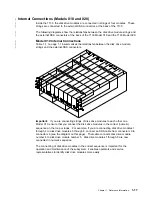
SSA Connectors of Models 010 and 500
|
At the back of the 7133 are eight SSA connectors for the external SSA cables. Each pair
|
of connectors is on a signal card that provides direct connection to a backplane assembly
|
in the 7133.
|
SSA Connectors of Models 020 and 600
|
At the back of the 7133 are eight SSA connectors for the external SSA cables. In Models
|
020 and 600, the signal cards as used in Models 010 and 500 have been replaced by
|
bypass cards, each of which has a pair of SSA connectors. Each bypass card provides
|
connections to the backplane assemblies of the 7133. If a bypass card loses both of its
|
external SSA connections, it automatically reconfigures the SSA loop so that the loop
|
remains complete.
|
For full details about the operation and configuration of bypass cards, see also “SSA
|
Bypass Cards (Models 020 and 600)” on page 1-38.
|
SSA Fibre-Optic Extender Feature
|
The SSA Fibre-Optic Extender feature permits the 7133 to be connected to SSA adapters
|
or other devices (for example, other 7133s) through pairs of fiber optic cables. Each end
|
of a pair of fiber optic cables is connected to a Fibre-Optic Extender. The Fibre-Optic
|
Extender can be plugged into the SSA connector of a device or adapter. See also “SSA
|
Fibre-Optic Extenders and Fiber Optic Cables” on page 1-14.
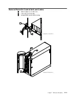
Remote Power On Control Feature
The Remote Power On Control feature permits the using system to control the electrical
power to the 7133. The feature consists of a control unit, a cable that connects the
control unit to the 7133, and cables that connect the control unit to the using system. See
also “Remote-Power-On Control Unit and Cables” on page 1-13.
|
−
48 Volt Power Supply (Model 020 Only)
|
The
−
48 Volt Power Supply feature provides fan-and-power supply assemblies and
|
three-way power cables that allow the 7133 to be connected to
−
48 volt power sources.
|
The 7133 must be connected to two separate power sources to ensure that operations are
|
not interrupted if one power source fails. Two three-way power cables are provided. This
|
feature is available only on Model 020.
1-2
7133 Service Guide
Summary of Contents for 7133 Series
Page 1: ...7133 SSA Disk Subsystems Service Guide SY33 0185 02...
Page 2: ......
Page 3: ...7133 SSA Disk Subsystems Service Guide SY33 0185 02...
Page 8: ...vi 7133 Service Guide...
Page 14: ...xii 7133 Service Guide...
Page 44: ...Labels Dummy Fan and Power Supply Assembly 1 30 7133 Service Guide...
Page 94: ...2 10 7133 Service Guide...
Page 110: ...2 2021 6 7133 Service Guide...
Page 114: ...2 2022 4 7133 Service Guide...
Page 138: ...2 2330 18 7133 Service Guide...
Page 146: ...2 16 7133 Service Guide...
Page 210: ...3 64 7133 Service Guide...
Page 222: ...4 12 7133 Service Guide...
Page 229: ......
Page 230: ...Part Number 32H6990 Printed in the United Kingdom 32H699 SY33 185 2...


