6
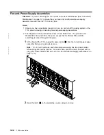
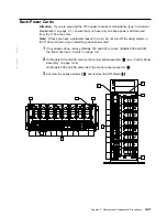
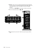
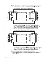
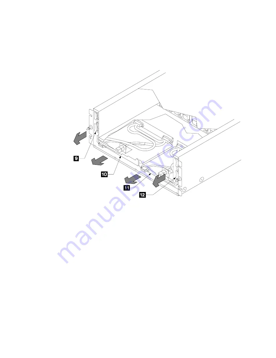
Each power-distribution tray assembly consists of a connector tray
1
or
11
and
a power card
9
or
12
. Pull the relevant power card forward until you feel it
release from the backplane connector.
|
Note: The diagram shows a 7133 Model 010. The procedure for Models 020, 500,
|
and 600 is the same, except that for Models 500 and 600, everything is turned
|
through 90 degrees.
7
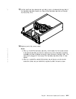
Carefully pull the complete power-distribution tray assembly out from the 7133.
8
Replace parts in the reverse order.
Note: When installing the power-distribution tray assembly, ensure that you push
both the connector tray and the power card fully home.
3-40
7133 Service Guide
Summary of Contents for 7133 Series
Page 1: ...7133 SSA Disk Subsystems Service Guide SY33 0185 02...
Page 2: ......
Page 3: ...7133 SSA Disk Subsystems Service Guide SY33 0185 02...
Page 8: ...vi 7133 Service Guide...
Page 14: ...xii 7133 Service Guide...
Page 44: ...Labels Dummy Fan and Power Supply Assembly 1 30 7133 Service Guide...
Page 94: ...2 10 7133 Service Guide...
Page 110: ...2 2021 6 7133 Service Guide...
Page 114: ...2 2022 4 7133 Service Guide...
Page 138: ...2 2330 18 7133 Service Guide...
Page 146: ...2 16 7133 Service Guide...
Page 210: ...3 64 7133 Service Guide...
Page 222: ...4 12 7133 Service Guide...
Page 229: ......
Page 230: ...Part Number 32H6990 Printed in the United Kingdom 32H699 SY33 185 2...


