background image


|

the label at the front of a disk drive module. The service aids show the number as the last

|

eight digits of the IEEE 16-digit SSA unique identifier (UID).

Service actions are always related to physical disk drives. For this reason, errors that
occur on SSA disk drives are always logged against the physical disk drive (pdisk).

If a disk drive that has been formatted on a machine of a particular type (for example, a
Personal System/2) is later installed into a using system that is of a different type (for
example, an RS/6000), that disk drive is configured only as a pdisk during the
configuration of the using system.

SSA Signal Cards (Models 010 and 500)

The four signal cards that are at the back of the 7133 Models 010 and 500 provide the
connections between the external SSA cables and the disk drive module strings. Each
signal card has two external SSA connectors. Through these connectors, the signal cards
and, therefore, the disk drive module strings, can be connected to each other or to the
using system.


Chapter 1. Reference Information

1-37

Summary of Contents for 7133 Series

Page 1: ...7133 SSA Disk Subsystems Service Guide SY33 0185 02...

Page 2: ......

Page 3: ...7133 SSA Disk Subsystems Service Guide SY33 0185 02...

Page 4: ...eriodically made to the information herein these changes will be incorporated in new editions of the publication It is possible that this publication may contain reference to or information about prod...

Page 5: ...1 2 Remote Power On Control Feature 1 2 48 Volt Power Supply Model 020 Only 1 2 Lights and Power Switch 1 3 Subsystem Lights and Power Switch 1 3 Disk Drive Module Lights 1 8 Parts Locations 1 10 Part...

Page 6: ...ls 010 and 500 1 44 Larger Configurations for Models 010 and 500 1 45 Cable Configurations for Models 020 and 600 1 51 Larger Configurations for Models 020 and 600 1 52 Finding the Physical Location o...

Page 7: ...nd Power Supply Assemblies 3 8 Power Model 020 with 48 V dc Fan and Power Supply Assemblies 3 10 Power Models 500 and 600 3 15 Disk Drive Modules 3 17 Removing a Module 3 17 Installing a Module 3 22 D...

Page 8: ...vi 7133 Service Guide...

Page 9: ...d grounded cables and connectors part numbers 07H9163 07H8985 32H1465 88G6404 32H1466 or 88G6406 or their equivalents must be used in order to meet FCC emission limits Neither the provider nor the man...

Page 10: ...ufacturer can accept responsibility for any failure to satisfy the protection requirements resulting from a non recommended modification of the product including the fitting of option cards not suppli...

Page 11: ...has the potential of causing moderate or minor personal injury This book contains a caution notice on each of the following pages 3 58 3 60 An attention notice indicates an action that could cause dam...

Page 12: ...lass 1 laser product that conforms to the requirements contained in the International Electrotechnical Commission IEC standard 825 1 1993 Class 1 laser products are not considered to be hazardous The...

Page 13: ...ering Convention In this book one gigabyte GB equals 1000000000 bytes Related Publications The Installation and Service Guide for your using system Diagnostic Information for Micro Channel Bus Systems...

Page 14: ...xii 7133 Service Guide...

Page 15: ...nts Models 020 and 600 always have three fan and power supply assemblies The disk drive modules are connected to each other in strings of four modules two strings at the front of the 7133 and two stri...

Page 16: ...at the loop remains complete For full details about the operation and configuration of bypass cards see also SSA Bypass Cards Models 020 and 600 on page 1 38 SSA Fibre Optic Extender Feature The SSA F...

Page 17: ...Unless otherwise stated the lights described in this section remain visible when the covers of the 7133 are installed The lights at the back of Models 010 and 020 are not visible when the back door o...

Page 18: ...Power Card light This green light is on when electrical power is present on the card The light is not visible when the front cover is installed 5 Fan and Power Check light This amber light comes on an...

Page 19: ...ing Permanently on Amber The bypass card is switched to Bypass state Permanently on Green The bypass card is jumpered for Forced Inline mode Off The bypass card is switched to Inline state Status of L...

Page 20: ...ll present in the fan and power supply assemblies if the 7133 is connected to the mainline power source 2 Subsystem Power light This green light is on when the power switch has been pressed to turn on...

Page 21: ...bypass card is connected to the SSA adapter 8 Mode light Model 600 only This light shows in which mode the bypass card is operating 9 Link Status Ready light Model 600 only This green light shows the...

Page 22: ...module and SSA adapter that are logically on each side of and next to this module are not connected or are missing The disk drive modules or module and SSA adapter that are logically on each side of a...

Page 23: ...e running or have failed The light comes on as soon as the disk drive module is turned on and goes off when the POSTs are complete If the light remains on for longer than one minute after the disk dri...

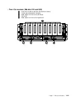
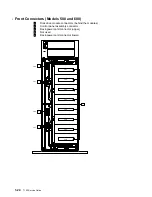
Page 24: ...ass card upper left Model 020 Bypass card upper right Model 020 14 Back power card on both sides 7 Front signal card right Model 010 15 Disk drive module lock optional Bypass card lower right Model 02...

Page 25: ...tion 3 15 RFI shield 6 Fan and power supply assy position 2 16 Lower power distribution tray assembly 7 Fan and power supply assy position 1 17 Upper power distribution tray assembly 8 Back cover 18 D...

Page 26: ...not contain disk drive modules 3 fan and power supply assemblies Dummy disk drive modules in all slots that do not contain disk drive modules Maximum 9 16 Maximum configuration always has redundant p...

Page 27: ...te Power On Control Unit and Cables Models 010 and 020 Models 500 and 600 1 Remote power on control unit 2 7133 power control cable 3 Using system power control cables Chapter 1 Reference Information...

Page 28: ...system or device via the fiber optic cable A wrap cable and adapter assembly 9 is provided with each Fibre Optic Extender This assembly consists of a fiber optic wrap cable 1 and a fiber optic wrap a...

Page 29: ...pter assembly must be kept in its plastic bag in a safe place that is as close to the Fibre Optic Extender as possible At least one wrap cable and adapter assembly must be kept at each end of the link...

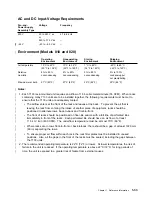
Page 30: ...J15 J14 J13 J15 J14 J13 J8 4 5 8 9 1 16 13 12 J7 J7 In the diagram each SSA connector 1 has two identification numbers The number that is preceded by a J for example J1 is used on Model 010 the numbe...

Page 31: ...onnecting strings of disk drive modules to each other on a Model 010 ensure that you connect the disk drive modules in the correct numeric sequence on the loop or loops For example if you are connecti...

Page 32: ...Model 020 Internal Connections Table 1 1 on page 1 16 summarizes the relationship between the disk drive module strings and the external SSA connectors 1 18 7133 Service Guide...

Page 33: ...n numbers The number that is preceded by a J for example J1 is used on Model 500 the number that is in parentheses for example 4 is used on Model 600 1 SSA connectors 4 Mainline power connectors 2 Dis...

Page 34: ...drive modules are connected in strings of four modules These strings are connected to the external SSA connectors at the back of the 7133 The following diagrams show the relationships between the disk...

Page 35: ...now connected in numeric sequence The connecting of disk drive modules in the correct sequence is important for the operation and maintenance of the subsystem it enables operators and service represen...

Page 36: ...utral Ground Live Neutral Ground Models 010 and 020 Models 500 and 600 Mainline Power Connector 48 V dc This type of connector is on each 48 V fan and power supply assembly Pin 1 Pin 7 Pin 12 Pin 6 Pi...

Page 37: ...3 J24 J25 J26 J27 J28 J30 J31 J30 J31 1 Disk drive module connectors behind the modules 2 Control panel assembly connector 3 Back power card connector left hand 4 Not used 5 Back power card connector...

Page 38: ...J21 J22 J23 J24 J25 J26 J27 J28 J30 J31 J30 J31 1 Disk drive module connectors behind the modules 2 Control panel assembly connector 3 Back power card connector upper 4 Not used 5 Back power card con...

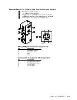
Page 39: ...ors 4 Using system auxiliary AUX power control connectors 5 Remote Power On Control Unit On Off switch Main MAIN Connector Pin Assignments Pin Assignment 1 Main power control 2 Main power control 3 Li...

Page 40: ...Pow er Light Pow er Light Pow er Light Pow er Light Pow er Light Control Panel Assembly Power Distribution Tray Assembly Power Distribution Tray Assembly Front Backplane Assembly Back Backplane Assemb...

Page 41: ...label 6 Empty position fan warning label 2 Fan 3 label 7 7133 serial number label 3 Empty slot disk warning label 8 Machine type and serial number label 4 Fan 2 label V C C I 1 Note The product infor...

Page 42: ...ng and 5 Machine type and serial number label product information label 6 Empty position fan warning label 2 Empty slot disk warning label 7 Fan 3 label 3 Fan 2 label 8 7133 serial number label 4 Fan...

Page 43: ...y disk drive modules that have a red panel can be used in a 7133 2 Dummy disk drive modules do not have a serial number label 1 Red panel see Note 1 2 Serial number see Note 2 3 Product information di...

Page 44: ...Labels Dummy Fan and Power Supply Assembly 1 30 7133 Service Guide...

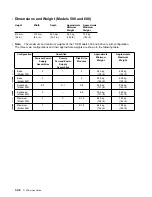
Page 45: ...26 2 in 36 0 kg 79 lb 50 0 kg 110 lb Configuration Quantities Approximate Minimum Weight Approximate Maximum Weight Fan and Power Supply Assemblies Dummy Fan and Power Supply Assemblies Disk Drive Mod...

Page 46: ...kg 129 lb 72 5 kg 160 lb Configuration Quantities Approximate Minimum Weight Approximate Maximum Weight Fan and Power Supply Assemblies Dummy Fan and Power Supply Assemblies Disk Drive Modules Base M...

Page 47: ...es at the back To prevent the air that is leaving the rack from entering the intake of another piece of equipment racks should be positioned in alternate rows back to back and front to front The front...

Page 48: ...nfiguration 480 watts 1638 Btu per hour Capacities of Disk Drive Modules The capacities that are given here for the different types of disk drive module apply when data is stored in 512 byte logical b...

Page 49: ...ed operating range see Environment Models 010 and 020 or Environment Models 500 and 600 on page 1 34 allow the disk drive module time to acclimate to the operating environment Remove the disk drive mo...

Page 50: ...the device disk drive module must be found by use of a service aid The service aid uses the IEEE standard 16 digit unique ID of the device Pdisks Hdisks and Disk Drive Module Identification The physi...

Page 51: ...System 2 is later installed into a using system that is of a different type for example an RS 6000 that disk drive is configured only as a pdisk during the configuration of the using system SSA Signa...

Page 52: ...nnectors is connected to a powered on SSA adapter or device it switches to Inline state that is it connects the internal SSA links to the external connector If the bypass card detects that neither of...

Page 53: ...line mode is used to disable the switching ability of selected bypass cards in particular types of subsystem configuration The types of configuration that might require Forced Inline mode are those in...

Page 54: ...en neighboring pins along its length The default setting is for Bypass mode The mode can be changed by swapping the positions of the jumpers For instructions on how to remove a bypass card and change...

Page 55: ...Jumpers Set for Forced Inline Mode J3 J4 1 SSA connectors 3 Jumpers 2 Backplane connectors 4 Bypass circuits Chapter 1 Reference Information 1 41...

Page 56: ...for SSA Loops Details of the rules for configuring SSA loops are given for each SSA adapter in the SSA Adapters User s Guide and Maintenance Information manual SSA loops that include disk drives that...

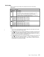
Page 57: ...cables Longer cables can obstruct the removal and replacement of the disk drive modules Table 1 3 SSA Cables Item Part Description 1 SSA adapter For information about the various types of SSA adapter...

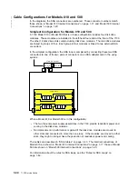
Page 58: ...ng these two SSA connectors to one of the two pairs of connectors on an SSA adapter card in the using system 7133 unit J10 J9 1 2 3 4 Using system A1 A2 B1 B2 When a Model 010 or Model 500 is in this...

Page 59: ...d 500 three fan and power supply assemblies must be present in the 7133 if redundant power and cooling for all the disk drive modules is required No improvement in performance is gained if the disk dr...

Page 60: ...adapter J10 J9 1 2 3 4 5 6 7 8 J6 J5 16 15 14 13 12 11 10 9 J2 J4 J1 J3 7133 unit Using system A1 A2 B1 B2 For this configuration three fan and power supply assemblies must be present in the 7133 The...

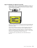
Page 61: ...in one loop but for better performance and better serviceability it is recommended that the disk drive modules be connected in two loops each of which is connected to a separate pair of connectors on...

Page 62: ...10 9 J2 J4 J1 J3 J10 J9 1 2 3 4 5 6 7 8 J6 J5 16 15 14 13 12 11 10 9 J2 J4 J1 J3 J10 J9 1 2 3 4 5 6 7 8 J6 J5 16 15 14 13 12 11 10 9 J2 J4 J1 J3 J10 J9 1 2 3 4 5 6 7 8 J6 J5 16 15 14 13 12 11 10 9 J2...

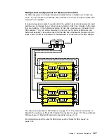
Page 63: ...sk drive modules This example shows one 7133 connected in one loop with two adapter cards 7133 unit J10 J9 1 2 3 4 5 6 7 8 J6 J5 16 15 14 13 12 11 10 9 J2 J4 J1 J3 Using system A1 A2 B1 B2 Using syste...

Page 64: ...s i n g s y s t e m B2 B1 A2 A1 A1 A2 B1 B2 U s i n g s y s t e m U s i n g s y s t e m B2 B1 A2 A1 A1 A2 B1 B2 7133 unit 1 J10 J9 1 2 3 4 5 6 7 8 J6 J5 16 15 14 13 12 11 10 9 J2 J4 J 1 J3 7133 unit...

Page 65: ...ked to two external SSA connectors In the simplest configuration the SSA loop is completed by connecting these two SSA connectors to one of the two pairs of connectors on an SSA adapter card in the us...

Page 66: ...nd 600 have three fan and power supply assemblies which provide redundant power and cooling to all the disk drive modules No improvement in performance is gained if the disk drive modules are moved to...

Page 67: ...13 5 9 16 All Models 020 and 600 have three fan and power supply assemblies which provide redundant power and cooling to all the disk drive modules No improvement in performance is gained if the disk...

Page 68: ...be connected in one loop but for better performance and better serviceability it is recommended that the disk drive modules be connected in two loops each of which is connected to a separate pair of...

Page 69: ...5 6 7 8 9 10 11 12 13 14 15 16 13 5 9 16 7133 unit 6 4 8 1 12 4 3 2 1 5 6 7 8 9 10 11 12 13 14 15 16 13 5 9 16 Using system A1 A2 B1 B2 7133 unit 2 4 8 1 12 4 3 2 1 5 6 7 8 9 10 11 12 13 14 15 16 13...

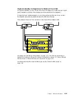
Page 70: ...The internal connections of Model 020 are shown in Model 020 Internal Connections on page 1 18 those of Model 600 are shown in Model 600 Internal Connections on page 1 21 For information about the rul...

Page 71: ...1 A2 B1 B2 U s i n g s y s t e m U s i n g s y s t e m B2 B1 A2 A1 A1 A2 B1 B2 7133 unit 2 4 8 1 12 4 3 2 1 5 6 7 8 9 10 11 12 13 14 15 16 13 5 9 16 7133 unit 1 4 8 1 12 4 3 2 1 5 6 7 8 9 10 11 12 13...

Page 72: ...Service Aids Are Available Finding the Device When No Service Aids Are Available When no service aids are available you must find the device by using the Port P and SSA address AA values that are prov...

Page 73: ...n of the complete system all the VPD files in the system are updated before any microcode is downloaded from the using system to the SSA subsystem If the using system later downloads a new level of mi...

Page 74: ...ations used in this section are FRU Field replaceable unit RAM Random access memory ROM Read only memory ROS Read only storage SSA Serial storage architecture 1 1 GB 2 2 GB 4 5 and 9 0 GB SSA Disk Dri...

Page 75: ...publications Inspection Checklist 1 Remove all power from the 7133 see All Power on page 3 7 2 Check the frame for damage loose broken or sharp edges 3 Check the power cable and ensure that a The thir...

Page 76: ...ervice Guide for the using system 2 Ensure that the power cable 1 is plugged into each fan and power supply assembly Ensure also that the other end of the power cable is plugged into the power distrib...

Page 77: ...ures and check the grounding of the 7133 Any test equipment must be connected to the frame of the 7133 If the grounding is not correct unplug the power cable from all the fan and power supply assembli...

Page 78: ...rvice Guide to isolate the fault Grounding Check Model 020 with 48 V Fan and Power Supply Assemblies 1 Ensure that all power is removed from the rack see the Installation and Service Guide for the usi...

Page 79: ...ew 6 Ensure that the screw 5 is tight 7 Follow your local procedures and check the grounding of the 7133 Any test equipment must be connected to the frame of the 7133 If the grounding is not correct u...

Page 80: ...r supply assembly for a new one see Fan and Power Supply Assemblies on page 3 32 then do the complete grounding check again If each fan and power supply assembly has continuity you might have a proble...

Page 81: ...and Service Guide to isolate the fault 12 Attention Each three way power cable must be connected to all three fan and power supply assemblies otherwise problems occur if one 48 volt power source fails...

Page 82: ...odel 600 has a three way power cable that consists of the standard one way power cable for your country 1 and a three way converter cable 2 Ensure that the two parts of the power cable are connected b...

Page 83: ...Unplug the cable if necessary 4 Attention Some electrical circuits could be damaged if the external SSA cables or power control cables are present at the 7133 while the grounding check is being done E...

Page 84: ...wer supply assembly and continue with step 10 10 Check for continuity between the frame of the 7133 and the ground pin 6 of the power connector on each fan and power supply assembly 11 If any fan and...

Page 85: ...includes tests of Microprocessor ROM Safety circuits If POST 1 completes successfully POST 2 is enabled If POST 1 fails the disk drive module Check light stays on and the disk drive module is not conf...

Page 86: ...umbers SRNs Service request numbers SRNs are generated for the 7133 by the system error log analysis system configuration code diagnostics and customer problem determination procedures SRNs help you t...

Page 87: ...of the 7133 Each card is plugged into the back backplane assembly and is connected by way of a cable to one of the power distribution tray assemblies Disk drive module A disk drive attached to a carri...

Page 88: ...rd or bypass card 2 Signal Cards and Bypass Cards on page 3 43 Description An SSA Threshold exceeded link error has been detected Action Go to the Intermittent Link Error MAP in the SSA Adapters User...

Page 89: ...e the link is broken The diagnostics show which disk drive module detected the problem 2FFFF None Description An async code that is not valid has been received Action Go to Software and Microcode Erro...

Page 90: ...the 7133 20 Description The SSA adapter has detected an open SSA loop Action If the SSA service aids are available run the Link Verification service aid see the chapter about SSA service aids in the...

Page 91: ...00 None Description The 7133 cannot be turned on Action Go to MAP 2020 7133 Power on page 2 2020 1 60210 Disk drive module 100 Disk Drive Modules on page 3 17 Description A disk drive module has its C...

Page 92: ...ore you run the diagnostics again You can observe the progress of the Format operation by running the Format service aid again on this disk drive module D0460 None Description A Format operation has b...

Page 93: ...the actions and answer the questions given in these MAPs When instructed to exchange two or more FRUs in sequence 1 Exchange the first FRU in the list for a new one 2 Verify that the problem is solve...

Page 94: ...2 10 7133 Service Guide...

Page 95: ...not turn off the using system when servicing the 7133 or an SSA link Power cables and external SSA cables that connect the 7133 to the using system can be disconnected while that system is running Ste...

Page 96: ...n control unit 3 Go to step 6 on page 2 2030 5 in MAP 2030 7133 Remote Power On Control Feature Step 3 from step 2 Have you been sent to this MAP from the Configuration Verification service aid NO Go...

Page 97: ...the pdisk 2 Go to step 7 Step 7 from step 6 Do you have an SRN NO The problem might have occurred because the formatting of the disk is not compatible with the using system Probably the disk has been...

Page 98: ...but the stand alone diagnostics are available 1 Run the stand alone diagnostics see Installing SSA Extensions to Stand Alone Diagnostics on page 2 1 2 Go to step 10 If neither the system diagnostics n...

Page 99: ...2 2010 7 YES Go to step 13 Step 13 from step 12 Does any fan and power supply assembly in the 7133 have its Fan and Power Check light on or flashing NO Go to step 14 on page 2 2010 6 YES If the Fan a...

Page 100: ...for a new one see Disk Drive Modules on page 3 17 2 Go to MAP 2410 7133 Repair Verification on page 2 2410 1 to verify the repair If the Check light is flashing it has been set by a service aid Check...

Page 101: ...tion on page 2 2410 1 to verify the repair Step 18 from step 12 Does any 7133 have its Subsystem Power light off NO Go to step 19 YES Go to step 21 on page 2 2010 8 Step 19 from step 18 Do you have an...

Page 102: ...e 2 11 to isolate the problem otherwise go to the SSA Link MAP in the SSA Adapters User s Guide and Maintenance Information manual Step 21 from step 18 Is the 7133 turned on check whether any disk dri...

Page 103: ...has sent you here Step 1 from step 21 in MAP 2010 7133 START Does the fan and power supply assembly in either position 2 or position 3 have its Power light on NO Go to step 2 YES Go to step 3 on page...

Page 104: ...n page 2 2410 1 to verify the repair 1 Control panel assembly see Control Panel Assembly on page 3 36 2 Left hand Models 010 and 020 or upper Models 500 and 600 power distribution tray assembly see Po...

Page 105: ...which disk drive module has Power status Although one of its power inputs is missing the disk drive module continues to work normally Attention Unless the using system needs to be turned off for some...

Page 106: ...dapters User s Guide and Maintenance Information manual 6 7 LINK VERIFICATION 8 2386 SSA Link Verification for ssa1 5 SSA Adapter To set or reset Identify move cursor onto selection then press Enter P...

Page 107: ...ge you go to MAP 2410 7133 Repair Verification on page 2 2410 1 to verify the repair 1 Disk drive module see Disk Drive Modules on page 3 17 2 The front backplane assembly if the disk drive module is...

Page 108: ...Step 3 from step 2 1 Observe the Power Card lights 1 2 3 and 4 Note which lights are on and which lights are off 2 Go to step 4 on page 2 2021 5 2 2021 4 7133 Service Guide...

Page 109: ...ght hand Models 010 and 020 or lower Models 500 and 600 power distribution tray assembly Power Distribution Tray Assemblies on page 3 38 On On Off On 1 Fan and power supply assembly in position 3 Fan...

Page 110: ...2 2021 6 7133 Service Guide...

Page 111: ...present from the 7133 see Dummy Fan and Power Supply Assembly Models 010 and 500 Only on page 3 34 4 Remove all the disk drive modules from the 7133 see Disk Drive Modules on page 3 17 5 Go to step 2...

Page 112: ...o to step 4 Step 4 from step 3 1 Reinstall the fan and power supply assembly or dummy fan and power supply assembly into position 1 2 If reinstalling a fan and power supply assembly connect the three...

Page 113: ...he next disk drive module into the slot from which it was originally removed Does the 7133 emit smoke or a smell of burning NO Go to step 7 YES 1 Exchange the disk drive module for a new one 2 Go to s...

Page 114: ...2 2022 4 7133 Service Guide...

Page 115: ...system can be disconnected while that system is running Step 1 from step 16 in MAP 2010 7133 START Is the power turned on at the using system NO The fan and power supply assemblies receive no power i...

Page 116: ...er supply assemblies that are present in the 7133 Does at least one Fan and Power Check light remain on NO 1 Reconnect the MAIN using system power control cables to the remote power on control unit 2...

Page 117: ...hort 7133 power control cable to connector J7 at the back of the 7133 2 In the sequence shown exchange the following FRUs for new FRUs Ensure that for each FRU exchange you go to MAP 2410 7133 Repair...

Page 118: ...red on exchange in the sequence shown the following FRUs for new FRUs Ensure that for each FRU exchange you go to MAP 2410 7133 Repair Verification on page 2 2410 1 to verify the repair a Remote power...

Page 119: ...fan and power supply assembly whose Power light is off and Fan and Power Check light is on see Fan and Power Supply Assemblies on page 3 32 2 Go to MAP 2410 7133 Repair Verification on page 2 2410 1 t...

Page 120: ...trol cables if previously removed 2 Disconnect the far ends of both MAIN power control cables from the device or power distribution unit to which they are connected 3 Observe the fan and power supply...

Page 121: ...both lights of each Fibre Optic Extender are on A wrap cable and adapter assembly 3 is provided with each Fibre Optic Extender This assembly consists of a fiber optic wrap cable 4 and a fiber optic w...

Page 122: ...rap adapter to make a closed loop If the wrap cable is 150 mm 6 in long one end of the cable is connected to the wrap adapter and protective covers are placed over each end of the complete wrap cable...

Page 123: ...e 2 2410 1 to verify the repair YES Go to step 2 Step 2 from step 1 step 10 on page 2 2330 12 and step 15 on page 2 2330 17 If you are at this step for the first time observe the lights on either of t...

Page 124: ...ck whether the fiber optic cables are crossed over that is one cable is connected to a Receive connector at each end and the other cable is connected to a Transmit connector at each end If the cables...

Page 125: ...es on page 3 17 For information about disk drive module strings see Internal Connections Models 010 and 020 on page 1 17 or Internal Connections Models 500 and 600 on page 1 20 2 If present the dummy...

Page 126: ...e strings see Internal Connections Models 010 and 020 on page 1 17 or Internal Connections Models 500 and 600 on page 1 20 b If present the dummy disk drive modules that are between the connector and...

Page 127: ...instructions until the microcode is installed See 4 on page 2 2330 2 if you need to load the microcode 2 In the next step you are going to disconnect the fiber optic cables Before you do so note the i...

Page 128: ...re Optic Extender 5 Go to MAP 2410 7133 Repair Verification on page 2 2410 1 to verify the repair Note If the problem remains find another wrap cable and adapter assembly and repeat this step The orig...

Page 129: ...onnect the fiber optic cables 1 from the Fibre Optic Extender 4 Find the wrap cable and adapter assembly that is provided with the Fibre Optic Extender 5 Remove the wrap cable and adapter assembly fro...

Page 130: ...f the complete wrap cable and adapter assembly 2 Place the wrap cable and adapter assembly into its plastic bag and return it to the place where it is normally kept 3 Exchange the Fibre Optic Extender...

Page 131: ...Extender and do whichever of the two following actions is appropriate If the wrap cable is 400 mm 15 in long connect each of its ends to the wrap adapter to make a closed loop If the wrap cable is 15...

Page 132: ...e first disk drive module on the string to which the Fibre Optic Extender is connected Is the Ready light on continuously NO Go to step 11 on page 2 2330 13 YES Go to step 10 Step 10 from step 9 The d...

Page 133: ...instructions until the microcode is installed See 4 on page 2 2330 2 if you need to load the microcode 2 In the next step you are going to disconnect the fiber optic cables Before you do so note the...

Page 134: ...bserving the identifications of the fiber optic cables connect the cables to the new Fibre Optic Extender 5 Go to MAP 2410 7133 Repair Verification on page 2 2410 1 to verify the repair Note If the pr...

Page 135: ...erving the identifications of the fiber optic cables reconnect the cables to the Fibre Optic Extender 4 Exchange in the sequence shown the following FRUs for new FRUs Ensure that for each FRU exchange...

Page 136: ...apter assembly into its plastic bag and return it to the place where it is normally kept 3 Observing the identifications of the fiber optic cables reconnect the cables to the Fibre Optic Extender Is t...

Page 137: ...s to the Fibre Optic Extender 4 Find the Fibre Optic Extender that is at the other end of the link 5 Go to step 2 on page 2 2330 3 YES 1 Remove the wrap cable from the Fibre Optic Extender and do whic...

Page 138: ...2 2330 18 7133 Service Guide...

Page 139: ...er steps 1 2 and 4 in MAP 2021 7133 Redundant Power steps 1 2 4 5 6 7 8 and 9 in MAP 2030 7133 Remote Power On Control Feature steps 1 5 6 7 8 11 13 14 and 15 in MAP 2330 7133 Fibre Optic Extender Bef...

Page 140: ...gnostics otherwise errors are logged on other using systems that share the same loop If the original problem was not reported by a device run diagnostics to each SSA adapter in the using system 2 Run...

Page 141: ...problem you can refer directly to the link status lights to isolate the failing FRU The descriptions given here show you how to do this In an SSA loop SSA devices are connected through two or more SS...

Page 142: ...33 It has five parts although the two backplane parts are on the same backplane assembly of the 7133 Backplane Dumm y Disk Drive 1 Backplane Disk Drive 2 7133 Example 3 This link is between two disk d...

Page 143: ...flashing green status light at each end of the affected link Some configurations have other indicators along the link for example on bypass cards or Fibre Optic Extenders to help with FRU isolation T...

Page 144: ...t is on when the 5 volt input is present Receive light This light when on shows that light is being received at the input connector of the Fibre Optic Extender The received light might not be a valid...

Page 145: ...ashing To help locate pdisk3 and pdisk1 select the pdisk and press Enter The Check light on the selected pdisk flashes This action does not affect the customer s operations For more information about...

Page 146: ...2 16 7133 Service Guide...

Page 147: ...is called concurrent maintenance Unless you have a particular reason to do so do not remove the power unless these instructions tell you to do so The following FRUs can be maintained concurrently in a...

Page 148: ...nt cover of a Model 500 or Model 600 Open the back cover of a Model 500 or Model 600 Models 010 and 020 have no back cover Note Unless you have a particular reason to do so do not turn off the using s...

Page 149: ...om of the cover and pull the cover forward 3 When installing the front cover ensure that the pins on the cover are correctly aligned with the clips on the frame of the 7133 Press both ends and the cen...

Page 150: ...pen the front cover hold it at the sides and pivot it downward 2 To remove the front cover assembly unscrew the five captive screws 1 and remove the front cover assembly 3 Replace parts in the reverse...

Page 151: ...vers 2 Insert the key into the lock 1 and turn the key counterclockwise 3 The cover is pivoted on its left hand side and is held closed by clips Pull strongly on the right hand side of the cover to re...

Page 152: ...e key to the covers 2 Insert the key into the lock 1 and turn the key counterclockwise 3 The cover is pivoted on its left hand side and is held closed by clips Pull strongly on the right hand side of...

Page 153: ...following tell you to This section has three parts Power Models 010 and 020 with 220 V Fan and Power Supply Assemblies on page 3 8 Power Model 020 with 48 V dc Fan and Power Supply Assemblies on page...

Page 154: ...2 Observe the Subsystem Power light 2 If the light is on open the flap that protects the power switch 1 On Model 010 the flap pivots upward on Model 020 it pivots to the right 3 On Model 010 press th...

Page 155: ...nce when the input voltage is inside the specified limits Their motors are started under control of the SSA adapters in the using system To prevent the need for excessive electrical current the disk d...

Page 156: ...sk drive modules in the 7133 are no longer available to the using system 2 Observe the Subsystem Power light 2 If the light is on open the flap that protects the power switch 1 The flap pivots to the...

Page 157: ...e present one for each three way power cable 3 If you want to isolate the 7133 from the power source remove both three way power cables 4 Attention Each three way power cable must be connected to all...

Page 158: ...ach to the using system It is the responsibility of the customer to ensure that the outlet is correctly wired and grounded to prevent an electrical shock During an electrical storm do not connect cabl...

Page 159: ...the switch to show that the power source must remain turned off Note The remainder of this section describes the general procedure for removing the power cable from the rack For more details refer to...

Page 160: ...ar c Attention When replacing a cable observe the connector labels Ensure that you connect the 48 V connectors to the circuit breaker terminal and the RET connectors to the return bus bar Replace part...

Page 161: ...bsystem Power light 2 If the light is on On Model 500 press the Power switch 1 and hold it pressed for two seconds On Model 600 press and release the Power switch 2 The Subsystem Power light goes off...

Page 162: ...trol of the SSA adapters in the using system To prevent the need for excessive electrical current the disk drive modules are not all started together A maximum of four disk drive modules in the front...

Page 163: ...the same except that for Models 500 and 600 everything is turned through 90 degrees 1 If you are removing the disk drive module under concurrent maintenance see Concurrent Maintenance on page 3 1 firs...

Page 164: ...drive module 5 The following information is displayed 6 7 Remove a Disk from an SSA RAID Array Type or select values in entry fields Press Enter AFTER making all desired changes Entry Fields SSA RAID...

Page 165: ...ts They might not all be connected to the same SSA loop Attach identifying labels to the modules if you want to b Choose any one disk drive module that is attached to the backplane assembly that you a...

Page 166: ...customer for the key 11 Insert the key into the lock turn it counterclockwise and remove the lock 12 Press upward behind the red panel 2 and open the handle 3 This action pulls the disk drive module p...

Page 167: ...that the correct airflow is maintained around the disk drive modules in the other slots If you are not going to install a disk drive module into the empty slot go to step 6 on page 3 30 in Dummy Disk...

Page 168: ...d 600 is the same except that for Models 500 and 600 everything is turned through 90 degrees 1 If you are reinstalling a disk drive module and the covers of the 7133 have not been reinstalled since yo...

Page 169: ...ck 1 ask the customer for the key b Insert the key into the lock turn it counterclockwise and remove the lock c Press upward behind the red panel 2 and open the handle 3 This action pulls the dummy di...

Page 170: ...der its base to prevent it from falling 5 Ensure that the handle 3 on the disk drive module is fully open 6 With one hand giving support to the base of the module engage the module in the groove 4 and...

Page 171: ...all the lock 6 and turn the key clockwise Return the key to the customer 9 Replace other parts in the reverse order 10 If the disk drive module is in Service Mode reset Service Mode see the chapter ab...

Page 172: ...l number of the disk drive module that you have just installed 15 The serial number is shown twice next to the new pdisk number and next to the new hdisk number Make a note of the new pdisk and hdisk...

Page 173: ...ou want for the new disk drive module for example hdisk7 27 If you want to remove from the system configuration pdisk numbers that are not used give the following command for pdisks that remain define...

Page 174: ...agrams in these instructions show a 7133 Model 010 The procedure for Models 020 500 and 600 is the same except that for Models 500 and 600 everything is turned through 90 degrees 1 If not already done...

Page 175: ...le 3 This action pulls the dummy disk drive module partially out of its slot 5 Carefully pull out the dummy disk drive module As the module comes out put one hand under its base to prevent it from fal...

Page 176: ...e is fully open b With one hand giving support to the base of the module engage the module in the groove 4 and push it into its slot The module stops before it is fully home c Close the handle 5 Press...

Page 177: ...d If the module has a lock install the lock 6 and turn the key clockwise Return the key to the customer 7 Replace other parts in the reverse order Chapter 3 Removal and Replacement Procedures 3 31...

Page 178: ...n these instructions show a 7133 Model 010 The procedure for Models 020 500 and 600 is the same except that for Models 500 and 600 everything is turned through 90 degrees 1 At the back of the 7133 unp...

Page 179: ...not try to repair or exchange any part of it Note For a translation of the following notice see the Safety Information manual DANGER Do not try to open the covers of the power supply component 4 Repla...

Page 180: ...mbly 2 The diagrams in these instructions show a 7133 Model 010 The procedure for Model 500 is the same except that everything is turned through 90 degrees 3 The dummy fan and power supply assembly ca...

Page 181: ...rs occur if a dummy fan and power supply assembly is not present in a 7133 that is in base or expanded configuration see Hardware Configurations on page 1 12 Replace parts in the reverse order If you...

Page 182: ...Covers on page 3 2 2 Unscrew the captive screw 1 Note The control panel assembly on the left hand side of the diagram is present on 7133s that have the early type of front cover The control panel asse...

Page 183: ...assembly 2 out of its runners 4 Unscrew the captive screw 3 5 Pull off the control panel assembly 4 Note If mainline electrical power is present in the 7133 the internal dc power turns on if previousl...

Page 184: ...ason to do so do not turn off the using system or the 7133 when removing or installing a power distribution tray assembly 1 If not already done remove if an early type or open if a late type the front...

Page 185: ...ly Disconnect the relevant back power card cable 5 or 6 from the power distribution tray assembly that you are removing Note The diagram shows a 7133 Model 010 The procedure for Models 020 500 and 600...

Page 186: ...7133 Model 010 The procedure for Models 020 500 and 600 is the same except that for Models 500 and 600 everything is turned through 90 degrees 7 Carefully pull the complete power distribution tray as...

Page 187: ...off the using system or the 7133 when removing or installing a back power card 1 If not already done remove Models 010 and 020 or open Models 500 and 600 the front cover see Covers on page 3 2 2 On M...

Page 188: ...rd cables unless the job you are doing needs you to do so for example the removal of a backplane assembly Disconnect the cable 8 or 7 for the back power card that you are removing 5 Pull out the relev...

Page 189: ...the 7133 are no longer available to the using system If you are removing a bypass card from a Model 020 or Model 600 check the configuration of the 7133 to find out which disk drive modules are affect...

Page 190: ...at you use the special screwdriver SSA tool part 32H7059 to unscrew them The screwdriver is supplied with the 7133 Note On Models 010 and 500 SSA connectors 1 and 2 are on the back signal cards SSA co...

Page 191: ...are now going to install a new signal card Model 010 or Model 500 go to step 10 on page 3 47 If you are now going to install a new bypass card or change the jumper settings on the card that you have j...

Page 192: ...oss its width is plugged into connector J4 Note The default setting of all new bypass cards is for Bypass mode b This diagram shows the jumpers set for Forced Inline mode J3 J4 For Forced Inline mode...

Page 193: ...itions of the jumpers on the new card Go to step 8 8 Unplug the jumpers from their connectors 9 Swap the positions of the jumpers to change to the other mode see steps 5a and 5b then go to step 10 10...

Page 194: ...it then check whether you have solved the original problem If the problem remains go to step 2 2 If not already done remove Models 010 and 020 or open Models 500 and 600 the front cover see Covers on...

Page 195: ...ignal cards To prevent damage to the SSA connector screws ensure that you use the special screwdriver SSA tool part 32H7059 to unscrew them The screwdriver is supplied with the 7133 b Remove the two f...

Page 196: ...7133 Unscrew the four captive screws 6 and remove the bracket assembly 7 12 Unscrew the four captive screws 8 Note The diagrams in these instructions show a 7133 Model 010 The procedure for Models 02...

Page 197: ...t tighten the four captive screws in the bracket assembly and the four captive screws in the backplane assembly until after you have reinstalled the power cards and signal or bypass cards The cards ca...

Page 198: ...l Power on page 3 7 4 Remove the two back power cards from the front of the 7133 see Back Power Cards on page 3 41 5 On Models 500 and 600 open the back cover see Back Cover Models 500 and 600 Only on...

Page 199: ...esent 7133 Models 010 and 020 The procedure for Models 500 and 600 is the same except that everything is turned through 90 degrees 10 If you are servicing a Model 020 or 600 remove the two self adhesi...

Page 200: ...s in the backplane assembly until after you have reinstalled the power cards and signal or bypass cards The cards can be plugged in more easily if the backplane assembly is free to move slightly b If...

Page 201: ...inline power source and you have not set the 7133 Power switch to Off the internal dc power turns on if previously turned off by the using system power control when you remove the cables 2 Remove the...

Page 202: ...3 Note If the 7133 is still connected to the mainline power source and you have not set the 7133 Power switch to Off the internal dc power turns on if previously turned off by the using system power...

Page 203: ...remained operational while you removed the remote power on control unit ensure that the power switch of the remote power on control unit that you are going to install is set to on before you reinstall...

Page 204: ...les from the back of the 7133 To prevent damage to the SSA connector screws ensure that you use the special screwdriver SSA tool part 32H7059 to unscrew them The screwdriver is supplied with the 7133...

Page 205: ...the all the disk drive modules see Disk Drive Modules on page 3 17 5 Loosen the two screws 1 and pivot the two clamp plates 2 away from the slots in the 7133 Chapter 3 Removal and Replacement Procedu...

Page 206: ...7133 by yourself Ask another service representative for aid With aid from another service representative pull the 7133 forward and remove it from the rack 8 Reinstall the 7133 in the reverse order No...

Page 207: ...rails go to step 3 3 The 7133 is four EIA1 units high Using the preinstallation planning information or other information supplied by the customer determine where you are going to locate the 7133 in t...

Page 208: ...support rail so that it is horizontal and push it forward so that the stud 2 enters the matching hole in the front of the rack c Check whether the support rail is horizontal a spirit level might be u...

Page 209: ...ack observe the threaded hole 6 in each of the support rails that you have just installed 7 Count seven holes upward from each threaded hole and install a nut clip 7 7 Holes Chapter 3 Removal and Repl...

Page 210: ...3 64 7133 Service Guide...

Page 211: ...s chapter lists and gives part numbers for the parts and FRUs of the 7133 Models 010 020 500 and 600 Conventions AR in the units column of the parts list denotes that the quantity used is as required...

Page 212: ...Models 010 and 020 SSA Disk Subsystems 10A 1 2 3 5 6 7 8 9 10 11 12 12 12 13 14 15 16 17 17 18 19 20 18 19 20 21 22 21 22 22 22 23 4 4A 4B 4 4A 4B 24 25 26 27 28 29 30 31 32 33 34 35 24A 1 A 10B 4 2 7...

Page 213: ...stem 2 GB SSA C Physical Disk Drive 8 88G6401 AR 4 5 GB 3 5 inch SSA disk drive module Name used by system 4 GB SSA C Physical Disk Drive 8 89H4940 AR 9 1 GB 3 5 inch SSA disk drive module Model 020 o...

Page 214: ...Assembly 1 continued 10A 1 2 3 5 6 7 8 9 10 11 12 12 12 13 14 15 16 17 17 18 19 20 18 19 20 21 22 21 22 22 22 23 4 4A 4B 4 4A 4B 24 25 26 27 28 29 30 31 32 33 34 35 24A 1 A 10B 4 4 7133 Service Guide...

Page 215: ...umber of the SSA adapter see the Failing Function Code List in the Diagnostic Information for Micro Channel Bus Systems manual 27 07H9160 1 7133 power control cable 28 67G5181 AR Remote power on contr...

Page 216: ...Assembly 2 7133 Models 500 and 600 SSA Disk Subsystems 22 23 24 25 26 1 2 3 4 5 6 7 8 11 9 13 14 15 8 10 12 17 18 19 20 21 16 16A 16A 27 28 16B 16B 4 6 7133 Service Guide...

Page 217: ...ule Model 600 only Name used by system 9 GB SSA C Physical Disk Drive 7 88G6369 AR Dummy disk drive module 8 88G6485 2 Back power card 9 07H8967 1 Front signal card long upper Model 500 9 32H5690 1 By...

Page 218: ...Assembly 2 continued 22 23 24 25 26 1 2 3 4 5 6 7 8 11 9 13 14 15 8 10 12 17 18 19 20 21 16 16A 16A 27 28 16B 16B 4 8 7133 Service Guide...

Page 219: ...le 0 6 m 2 0 ft Model 500 only 20 07H8985 AR External SSA copper cable 1 0 m 3 3 ft 20 32H1465 AR External SSA copper cable 2 5 m 8 2 ft 20 88G6404 AR External SSA copper cable 5 0 m 16 4 ft 20 32H146...

Page 220: ...Netherlands Antilles Panama Phillipines Saudi Arabia Suriname Taiwan Trinidad United States except Chicago Venezuela 6952300 Chicago 6952301 Bahrain NEO Brunei China Ghana Hong Kong Iraq Ireland Jord...

Page 221: ...Indonesia Kazakhstan Lebanon FYR Macedonia Moldavia Netherlands Norway Portugal Romania Russia Serbia Slovakia Slovenia Spain Sudan Sweden Turkey Ukraine 13F9979 Israel 14F0087 Switzerland 14F0051 Ban...

Page 222: ...4 12 7133 Service Guide...

Page 223: ...replacement 3 52 back 3 52 backplane assembly front location Models 010 and 020 1 10 backplane assembly front continued location continued Models 500 and 600 1 11 removal and replacement 3 48 books r...

Page 224: ...00 location 1 11 locks 1 11 numbering Models 010 and 020 1 10 disk drive modules continued numbering continued Models 500 and 600 1 11 POSTs power on self tests 2 1 Power light 1 8 power sequencing 1...

Page 225: ...modules 1 36 indicators 1 3 disk drive module Check light 1 9 disk drive module Power light 1 8 indicators continued disk drive module Ready light 1 8 Fan and Power Check Models 010 and 020 1 4 Model...

Page 226: ...wer On Control Feature 2 2030 1 MAP 2330 7133 Fibre Optic Extender 2 2330 1 MAP 2410 7133 Repair Verification 2 2410 1 mechanical hazards 1 61 microcode and software errors 2 8 microcode maintenance 1...

Page 227: ...ers 2 2 FRU names used in table 2 3 SSA link 2 11 product characteristics 1 31 product information label 1 61 Models 010 and 020 1 27 Models 500 and 600 1 28 publications related xi R Ready light disk...

Page 228: ...SSA loops disk drive module identification 1 36 finding the physical location of a device 1 58 SSA loops and links 1 2 SSA system configurations 1 42 stand alone diagnostics SSA extensions to installi...

Page 229: ......

Page 230: ...Part Number 32H6990 Printed in the United Kingdom 32H699 SY33 185 2...

Reviews: