|
Bypass Card Jumpers
|
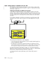
The mode in which the bypass card operates is set by two jumpers. One jumper has links
|
between neighboring pins across its width; the other jumper has links between neighboring
|
pins along its length. The default setting is for Bypass mode. The mode can be changed
|
by swapping the positions of the jumpers. For instructions on how to remove a bypass
|
card and change its mode, see “Signal Cards and Bypass Cards” on page 3-43.
|
Jumpers Set for Bypass Mode
J3
J4
|
1
|
SSA connectors
|
3
|
Jumpers
|
2
|
Backplane connectors
|
4
|
Bypass circuits
1-40
7133 Service Guide
Summary of Contents for 7133 Series
Page 1: ...7133 SSA Disk Subsystems Service Guide SY33 0185 02...
Page 2: ......
Page 3: ...7133 SSA Disk Subsystems Service Guide SY33 0185 02...
Page 8: ...vi 7133 Service Guide...
Page 14: ...xii 7133 Service Guide...
Page 44: ...Labels Dummy Fan and Power Supply Assembly 1 30 7133 Service Guide...
Page 94: ...2 10 7133 Service Guide...
Page 110: ...2 2021 6 7133 Service Guide...
Page 114: ...2 2022 4 7133 Service Guide...
Page 138: ...2 2330 18 7133 Service Guide...
Page 146: ...2 16 7133 Service Guide...
Page 210: ...3 64 7133 Service Guide...
Page 222: ...4 12 7133 Service Guide...
Page 229: ......
Page 230: ...Part Number 32H6990 Printed in the United Kingdom 32H699 SY33 185 2...


