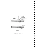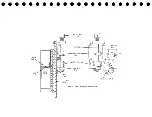
The load-point reflective spot is sensed and R25 picks. Relay 25-3n /c points
open, dropping R12. Relay 1 2 -ln /o points open, dropping +48 volts to manual r e
verse and manual start. This causes the tape drive to stop setting in a loaded con
dition.
23.2
MANUAL CONTROL OF TAPE MOTION
The following section deals with the manual control of tape motion, using the
customer engin eers switch and the load-rewind button.
With the C .E . switch set to FORWARD GO, +48 volts is available to pick R27
from R 12-5n /c, RIAU n/o, R 1 3 -ln /c , C .E . switch, R 6A Ln/c, R 5ALn/c, R 15-4n /c,
to the R27 coil. In this case, +48 volts is blocked from "manual reverse" by diode
D5. Relay 2 7 -ln /o closes to bring up the manual start line. The up level on man
ual start conditions the top leg of AND circuit T03JF27F (76. 05. 01). The bottom
leg is conditioned by "not arriving at load point." The resulting up level from F27F
carries through OR circuit T03JE29F and brings down the stop line through inverter
T03J7B. Tape starts feeding in a forward direction at this time.
The plus shift on the start line is also fed to the bottom leg of AND circuit
T04JG20F (76. 04). An up level results from G20F because the top leg is condi
tioned by "At L . P . " This up level causes relay driver T04J5B to pick relay 26.
Relay 2 6 -ln /o closes to furnish +48 volts to the R25 latch trip coil.
Relay 25 returns to normal and the R 25-4n/o points open to bring down "At
L . P . " to AND circuit G20F (76.04). This results in a down level to the relay
driver T04J5B, allowing R26 to fall.
With the C .E . switch set to stop, R27 is allowed to fall. This brings down the
manual start line and the tape is stopped.
With the C .E . switch set to BACKWARD GO, +48 volts is applied to the manual
reverse line through the 2 5 -ln /c and the 9 -3 n /c points. Relay 27 is picked through
the diode D5, R6A Ln/c, R 5A Ln/c, and R 15-4n /c points. Conditioning the manual
reverse line causes the tape to drive backward, from the right reel to the left reel.
Turning the C .E . switch to stop brings down "manual reverse" and "manual start",
causing the tape to stop again.
Depressing the load rewind button conditions the lower leg of AND circuit
T03JB30F (76. 08). The top leg is conditioned by read status and the resulting up
level causes relay 21 to be picked by relay driver T03J4B. Relay 2 1 -ln /o points
close to pick R3 and R3BUn/o closes to pick R9. Relay 12 is picked because of
the R 9-5n/o points closing and it is held by the R 12-2n/o points through diode D2.
The load point reflective spot being read causes R25 to be latch picked, R 25-3n /c
opens to drop R12. Relay 1 2 -ln /o opens to drop R27 and +48 to the manual reverse
line. The tape drive stops, setting in loaded condition with the load-point reflective
spot under the photo cell.
23.3
TAPE MOTION UNDER CALCULATOR CONTROL
Tape motion can be controlled from the computer programming. A control
0002 instruction in the 705 CPU causes the start rewind line to condition the upper
120
Summary of Contents for 727
Page 6: ......
Page 67: ...co Q...
Page 68: ......
Page 69: ...To Fuse 13 48V...
Page 70: ......
Page 71: ......
Page 72: ......
Page 73: ...o IC To Fuse 13 48V...
Page 74: ......
Page 75: ......
Page 76: ......
Page 78: ......
Page 92: ......
Page 93: ...039 0035 FIGURE 1 BIT PO SITIO N S O N TAPE CURRENT GENERATOR FIGURE 3c...
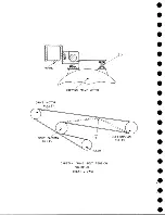
Page 95: ...w PATH OF TAPE THROUGH MACHINE FIGURE 6...
Page 97: ...SPLIT IDLER ASSEMBLY FIGURE 8...
Page 98: ......
Page 99: ...CLUTCH HOUSING POWDERED IRON AND GRAPHITE MIXTURE FIGURE 10 MAGNETIC CLUTCH...
Page 100: ...PUSH ROD DIAPHRAGM VACUUM COLUMN SWITCHES FIGURE II...
Page 101: ...BACKWARD MOTOR CAPSTAN MOTOR FORWARD MOTOR...
Page 102: ...LATCH FIGURE f3...
Page 103: ...140 140...
Page 107: ...FIGURE 18 HEAD ASSEMBLY A DJUSTM ENTS...
Page 108: ...TAPE C LEA N ER FIG URE 19...
Page 109: ...VACUUM COLUMN ADJUSTMENT FIG U RE 22...
Page 110: ...DRIVE MOTOR PULLEY CAPSTAN DRIVE BELT TENSION FIGURE 23 REAR VIEW S...
Page 113: ...CONTROL UNIT TAPE DRIVE TESTER FIGURE 28 TAPE DRIVE TESTER CO NN EC TIO N S...
Page 116: ...FIGURE 32 HIGH SPEED REWIND...
Page 135: ......
Page 136: ...v n...
Page 137: ......
Page 138: ......
Page 139: ......
Page 140: ......
Page 141: ......
Page 142: ......
Page 143: ......
Page 144: ......
Page 145: ......
Page 146: ......
Page 147: ......
Page 148: ......
Page 149: ......
Page 150: ......
Page 151: ......
Page 152: ......
Page 153: ......
Page 154: ......
Page 155: ......
Page 156: ......
Page 157: ......
Page 158: ......
Page 159: ......
Page 160: ......
Page 161: ......
Page 162: ......
Page 163: ......

